

Rfid Tag Having a Folded Dipole
- Summary
- Abstract
- Description
- Claims
- Application Information
AI Technical Summary
Benefits of technology
Problems solved by technology
Method used
Image

Examples
first embodiment
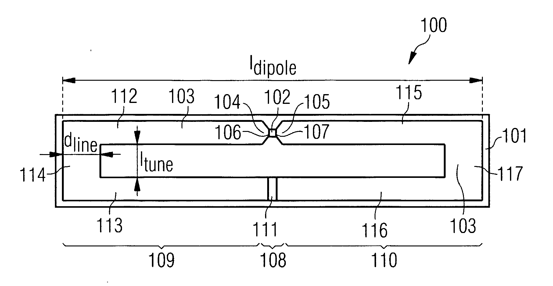
[0065]In the following, referring to FIG. 1, an RFID tag 100 according to the invention will be described in detail.
[0066]The RFID tag 100 comprises a plastics substrate 101 and an electrically conducting folded dipole antenna 103 arranged on the plastics substrate 101. The folded dipole antenna 103 has a first antenna connection 104 and has a second antenna connection 105. The RFID tag 100 further comprises a silicon chip 102 (i.e. an electronic chip made from a silicon wafer, the chip having an integrated circuit therein), wherein the silicon chip 102 is arranged on the plastics substrate 101. The silicon chip 102 has a first chip connection 106 connected to the first antenna connection 104 and has a second chip connection 107 connected to the second antenna connection 105. The folded dipole antenna 103 has a disconnected antenna portion 108 dividing the folded dipole antenna 103 in a first antenna portion 109 and in a second antenna portion 110 such that a capacity is formed as t...
second embodiment
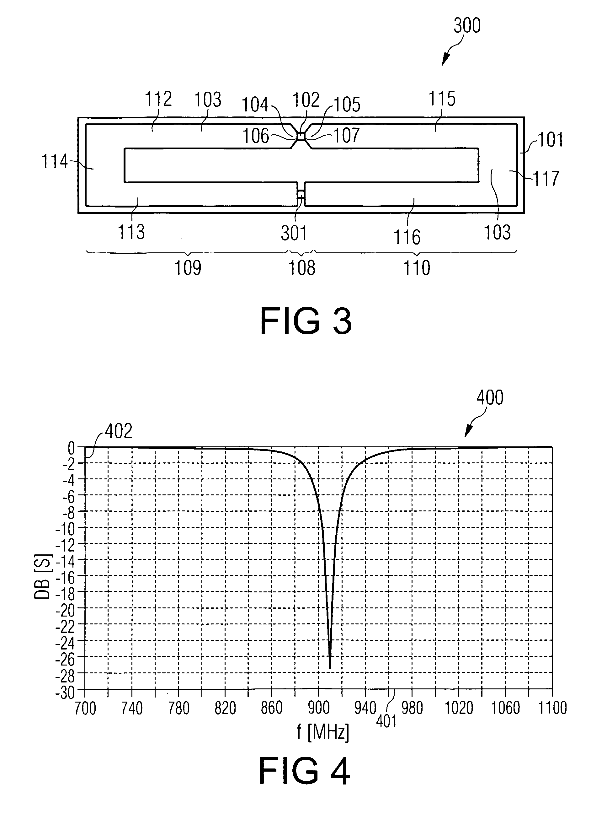
[0084]In the following, referring to FIG. 3, an RFID tag 300 according to the invention will be described.
[0085]The RFID tag 300 shown in FIG. 3 differs from the RFID tag 100 shown in FIG. 1 in that the disconnected antenna portion 108 is not filled with dielectric material 111 in the case of the RFID tag 300. According to FIG. 3, the first antenna portion 109 is bridged to the second antenna portion 110 in the disconnected antenna portion 108 by providing an SMD capacitor element 301 (“surface mounted device”). Therefore, the RFID tag 300 comprises a capacitor device 301 arranged in the disconnected portion 108, wherein the capacitor member 301 has a first capacitor connection connected to the first antenna portion 109 and has a second capacitor connection connected to the second antenna portion 110.
[0086]Thus, FIG. 3 shows an embodiment of the invention in which a short circuit of the rectifier circuit in an input portion of the transponder chip 102 is avoided by means of the SMD ...
third embodiment
[0091]Next, referring to FIG. 5, an RFID tag 500 according to the invention will be described.
[0092]In the case of the RFID tag 500 a first antenna portion is formed by a first leg 112 and a second leg 501 and a link piece 114 and a second antenna portion is formed by a first leg 115 and a second leg 502 and a link piece 117.
[0093]The RFID tag 500 shown in FIG. 5 differs from the RFID tag 100 shown in FIG. 1 in that no dielectric material 111 is provided between the second leg piece 501 of the first antenna portions and the second leg piece 502 of the second antenna portion in an area, in which the first and the second antenna portions are adjacent to one another. Further, in FIG. 1, the second legs 113, 116 have adjoining lines or areas, which are oriented perpendicular to alignment directions of the second legs 113, 116. In contrast to this, in FIG. 5, the adjoining lines or areas of the second leg pieces 501, 502 are aligned parallel to the alignment direction of the second leg p...
PUM
| Property | Measurement | Unit |
|---|---|---|
| Length | aaaaa | aaaaa |
| Dielectric polarization enthalpy | aaaaa | aaaaa |
| Shape | aaaaa | aaaaa |
Abstract
Description
Claims
Application Information