Cabling for Rack-Mount Devices

a rack-mount device and cabling technology, applied in the direction of coupling device connection, electrical apparatus casing/cabinet/drawer, instruments, etc., can solve the problems of data cables themselves adding latency to data communications between components, difficult maintenance of cables, etc., to achieve the effect of reducing the length and number of cables and increasing data rates

Active Publication Date: 2008-08-07
SANDISK TECH LLC
View PDF3 Cites 51 Cited by
  • Summary
  • Abstract
  • Description
  • Claims
  • Application Information

AI Technical Summary

Benefits of technology

[0008]Embodiments of the present invention advantageously decrease both the length and number of cables needed to interconnect rack mounted electronic components. Furthermore, in some embodiments, the interconnect strip enables optical connections between components. Optical connections via optical fiber permit digital communications over larger distances and at higher data rates than electronic components. In some embodiments, the system provides electrical-optical transceivers for receiving an optical signal via an uplink port and transmitting electrical signals across the plurality of data signal paths of the interconnect strip and vice versa. In other embodiments the system is adapted to receive electrical signals via an uplink port and convert the electrical signals to optical signals with an electrical-optical transceiver. In yet other embodiments, the system provides electrical-optical transceivers integrated into the interconnect strip for receiving electrical data signals from rack mounted devices and transmitting optical signals across the plurality of data signal paths of the interconnect strip and vice versa. In other embodiments, the electrical-optical transceivers are built into rack mounted electronic components and the rack mounted electronic components are coupled to the interconnect strip via an optical connection.

Problems solved by technology

As the number of components in the rackmount system increases, the number of and length of the data cables can make the cables difficult to maintain.
However, the cables still must be custom cut to the proper length by hand, and tracking down of faults in the system can become extremely difficult.
Furthermore, the data cables themselves can add latency to data communications between components.
As the length of data cables increases, electrical signals must travel across longer lengths of cable which not only increases the length of time that signals take to reach their destination, but may also increase the likelihood of distortion, noise, and / or interference detrimentally affecting signal quality.
Thus, blade server systems require specialized electronic devices designed to operate with blade server systems, and typical rackmount devices such as rackmount computer servers are not compatible with blade server systems.
Therefore, blade server systems are not always adequate solution for implementing computer server systems.

Method used


Image

  • Cabling for Rack-Mount Devices
  • Cabling for Rack-Mount Devices
  • Cabling for Rack-Mount Devices

Examples


Embodiment Construction

[0022]Embodiments of the invention are described here, with reference to the figures. Where elements of the figures are called out with reference numbers, it should be understood that like reference numbers refer to like elements and might or might not be the same instance of the element.

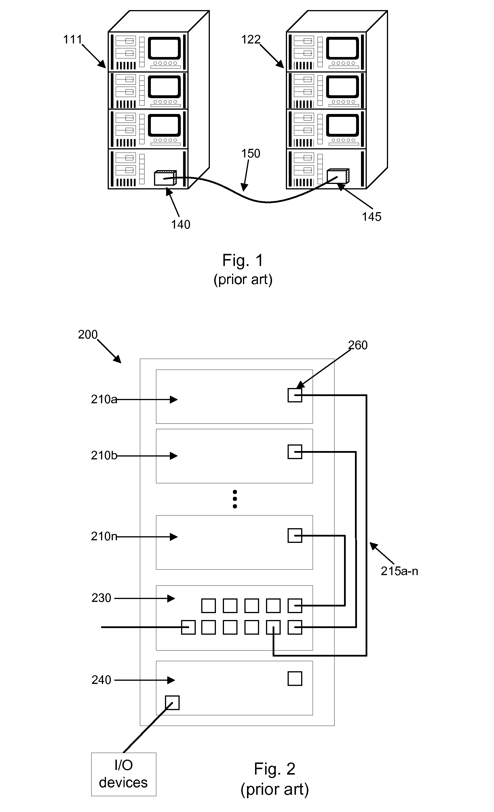
[0023]FIG. 1 is a block diagram of prior art rackmount systems. Rackmount systems 111 and 122 are connected by a data cable 150 which is coupled to rackmount system 111 via data connector 140 and coupled to rackmount system 122 via data connector 145. Data cable 150 enables electronic devices mounted in rackmount system 111 to communicate with electronic devices mounted in rackmount system 122 and vice versa. Data cable 150 carries electrical data signal. Data cable 150 may comprise any cable adapted to carrying electrical data signals, such as twisted pair or coaxial cable.

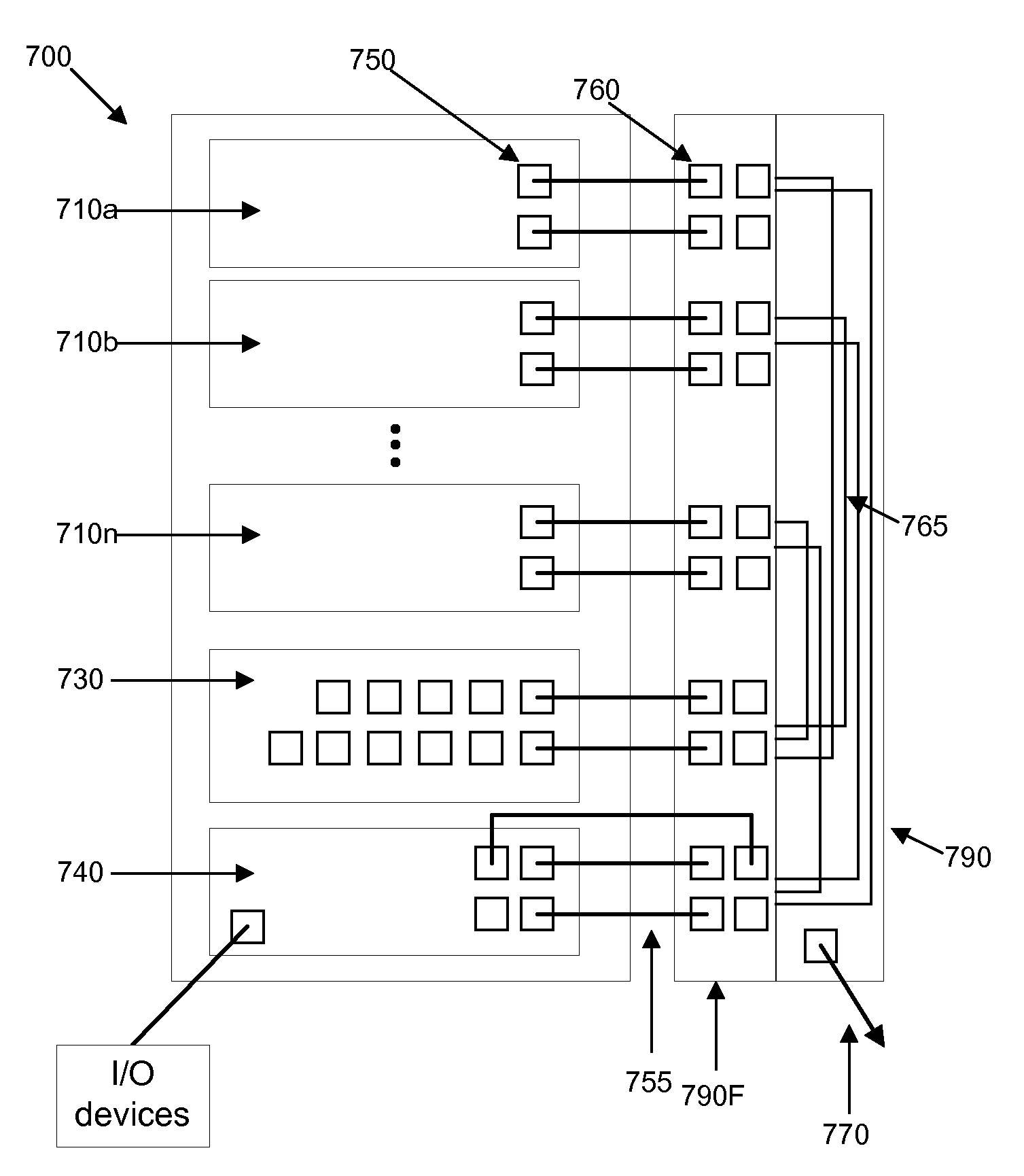
[0024]FIG. 2 is a block diagram of typical prior art rackmount system. Rackmount system 200 comprises an external cabinet inclu...


PUM


Abstract

A connector module is provided that includes a longitudinal body adapted for installation in a computer equipment rack capable of housing a plurality of server units positioned in a stack configuration. The longitudinal body has a plurality of data connectors mounted along an outer surface. Each data connector is located at a different location along the outer surface of the longitudinal body and is adapted to receive a signal source introduced from a front side of the outer surface. The connector module includes a collection of signal paths coupled to the plurality of data connectors. Signal paths are positioned toward a backside of the outer surface. The longitudinal body is adapted for installation in a transverse orientation relative to the plurality of server units in the stack configuration such that each data connector is positioned in proximity to a connector mounted on a corresponding one of the server units.

Description

CROSS-REFERENCES TO RELATED APPLICATIONS[0001]This application is related to co-owned and co-pending U.S. patent application Ser. No. 11 / ______, attorney docket number 026529-000300US, which is hereby incorporated by reference.BACKGROUND OF THE INVENTION[0002]Rack mount systems are standardized systems for mounting electronic equipment such as computer servers in a vertical, stacked configuration. For example, a common standard rack mount system is the 19 inch rack system (Electronic Industries Alliance—EIA 310-D) so named because the overall rack width in the system is 19 inches. A rackmount system typically comprises a cabinet with an open front and back which allows access to electronic components mounted in the rackmount system and encourages dissipation of excess heat from the electronic devices. A typical rackmount system, such as a 19-inch rack system, includes a set of parallel rails that runs vertically along the front of the cabinet. The rails are pierced at regular interv...

Claims


Application Information

Patent Timeline
Patent Type & Authority Applications(United States)
IPC IPC(8): H05K7/02
CPCH05K7/1492
Inventor VERDIELL, JEAN-MARCKIRKPATRICK, PETEREPITAUX, MARC
Owner SANDISK TECH LLC
Why Eureka
Try Eureka