
Methods and apparatus for calibrating output voltage levels associated with current-integrating summing amplifier

Inactive Publication Date: 2008-08-07
GLOBALFOUNDRIES US INC
View PDF3 Cites 78 Cited by
  • Summary
  • Abstract
  • Description
  • Claims
  • Application Information

AI Technical Summary

Benefits of technology

[0013]Principles of the invention provide improved techniques f

Problems solved by technology

However, the need to maintain feedback loop stability does entail compromises in the bandwidth of a closed-loop amplifier, so open-loop summing amplifiers are usually a more practical choice at very high signal frequencies (e.g., above 1 GHz).
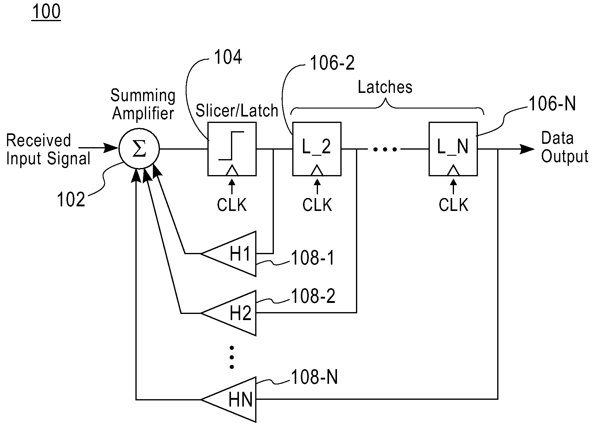
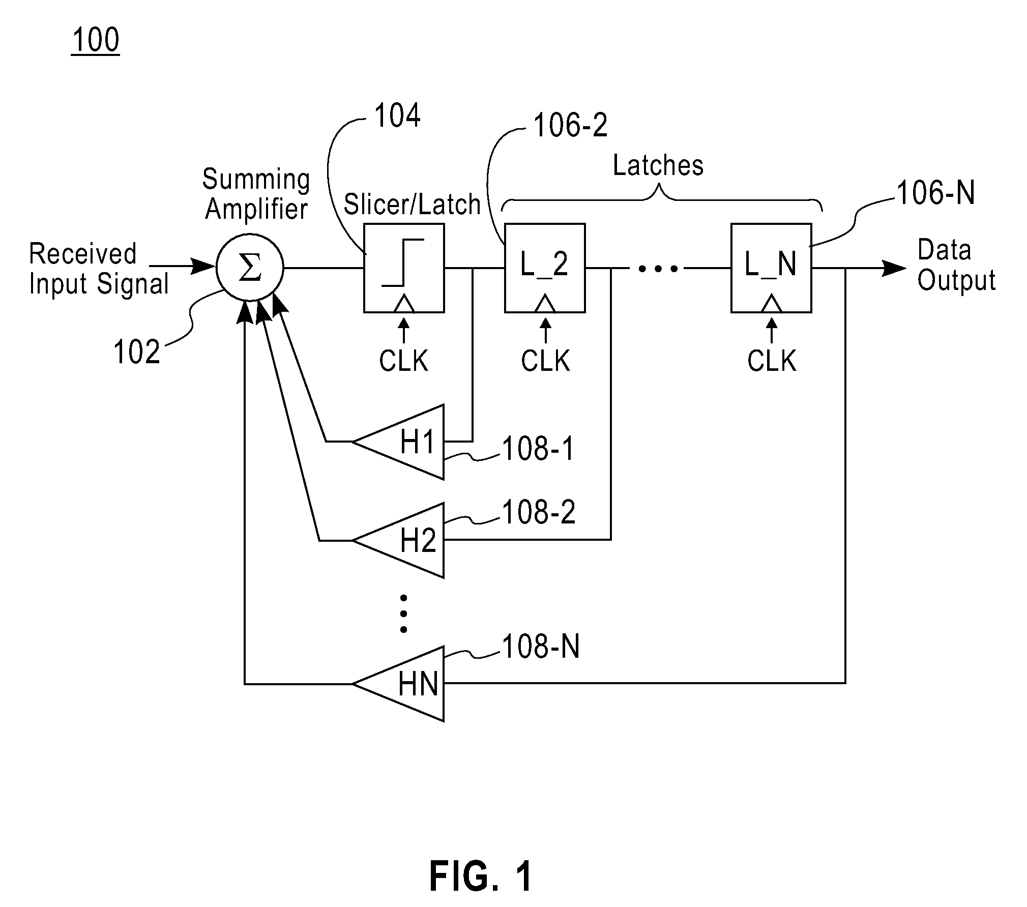
Due to limited channel bandwidth, the electrical pulses (representing bits) transmitted over a serial link are broadened over more than one unit interval (UI), and the received signal suffers from intersymbol interference (ISI).
A drawback of such resistive loading is relatively high power dissipation.
To meet amplifier gain and voltage swing requirements, however, the reduction in R must be accompanied by a commensurate increase in operating currents, leading to higher power dissipation.
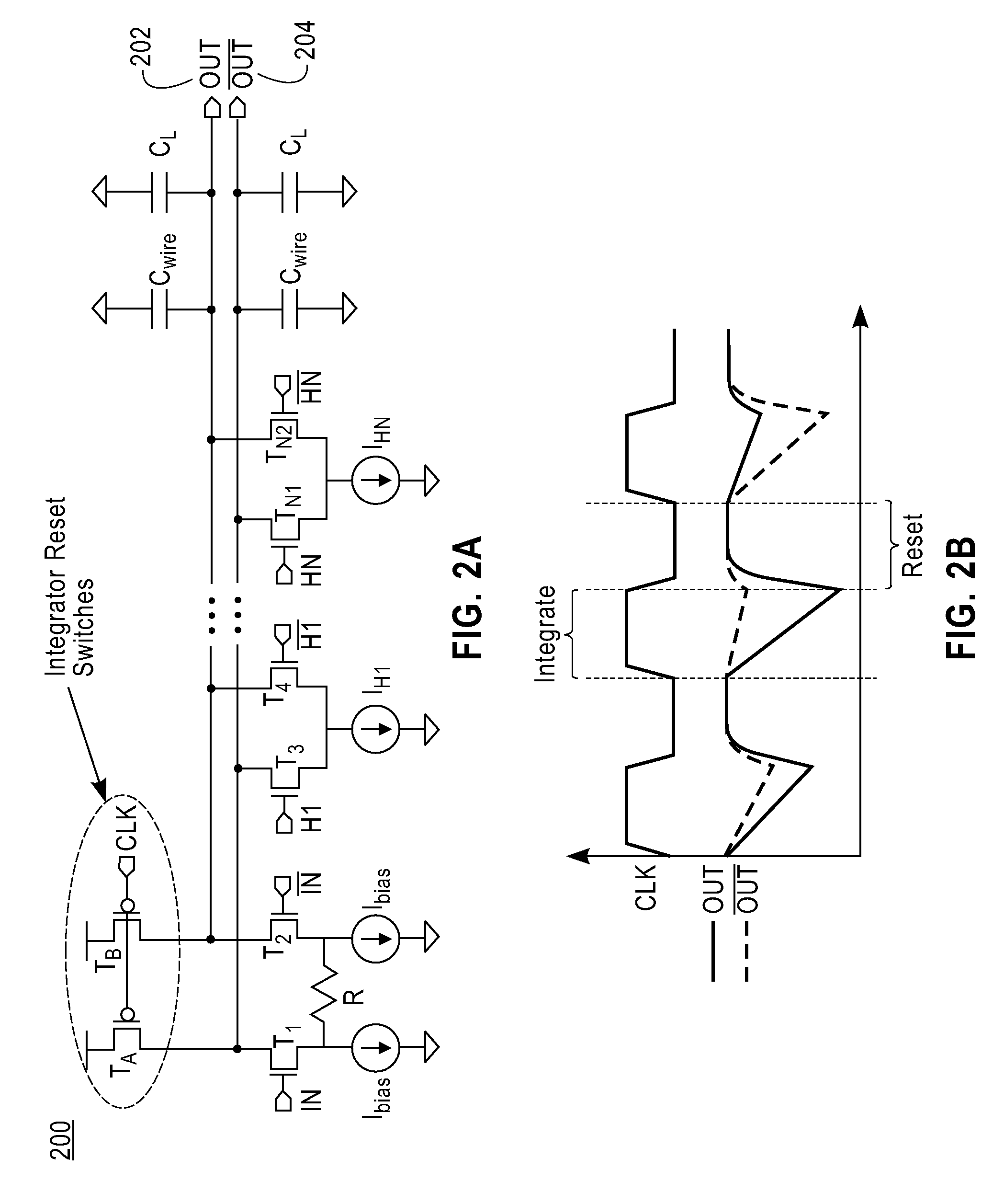
An important penalty of integrating currents onto parasitic capacitances is that the output voltage levels of the summer are highly sensitive to process variations.
While the replica feedback biasing scheme described in S. Sidiropoulos et al. does stabilize the output voltage levels of an integrating receiver with a single input, a circuit for calibrating a current-integrating summing amplifier with multiple inputs has not been shown to date.

Method used


Image

  • Methods and apparatus for calibrating output voltage levels associated with current-integrating summing amplifier
  • Methods and apparatus for calibrating output voltage levels associated with current-integrating summing amplifier
  • Methods and apparatus for calibrating output voltage levels associated with current-integrating summing amplifier

Examples


Embodiment Construction

[0027]Principles of the invention realize that, for accurate signal processing, it is desirable that the output signal component due to each input have a calibrated magnitude. However, it is also realized that, for sake of hardware efficiency, the complexity of such a calibration circuit should not grow significantly as the number of summer inputs is increased. Thus, as an example, one would not want to use a separate replica bias circuit of the type described in the above-mentioned S. Sidiropoulos et al. article to calibrate each summer input.

[0028]Accordingly, as will be illustratively described below, principles of the invention provide an improved calibration circuit for stabilizing the output voltage levels of a current-integrating summing amplifier wherein a single replica bias circuit is used to calibrate the output signal components due to multiple inputs. The calibration circuit includes a duplicate integrator with loads matched to the integrators in the main signal paths. ...


PUM


Abstract

Methods and apparatus are disclosed for calibrating summing amplifiers based on current integration. For example, apparatus for calibrating output voltage levels of a current-integrating summing amplifier includes the following components. A duplicate integrator circuit is provided, wherein the duplicate integrator circuit replicates an integrator circuit of the current-integrating summing amplifier. A comparing circuit, coupled to the duplicate integrator circuit, is provided for comparing at least one output voltage level generated by the duplicate integrator circuit with a reference voltage level. A feedback loop circuit, coupled to the comparing circuit and the duplicate integrator circuit, is provided for adjusting at least one bias signal of the duplicate integrator circuit so that the output voltage level generated by the duplicate integrator circuit matches the reference voltage level, wherein the bias signal is applied to the integrator circuit of the current-integrating summing amplifier thereby calibrating output signal components due to multiple input signals of the current-integrating summing amplifier.

Description

[0001]This invention was made with Government support under Contract No. H98230-04-C-0920 awarded by the National Security Agency. The Government has certain rights in this invention.FIELD OF THE INVENTION [0002]The present invention relates generally to the design of analog amplifiers for signal processing and specifically to techniques for calibrating summing amplifiers based on current integration.BACKGROUND OF THE INVENTION [0003]A basic building block employed in many analog and mixed-signal electronic systems is the summing amplifier, or summer, which adds together two or more analog signals. At lower frequencies, an accurate summer can be realized as a closed-loop circuit based around a high-gain operational amplifier. However, the need to maintain feedback loop stability does entail compromises in the bandwidth of a closed-loop amplifier, so open-loop summing amplifiers are usually a more practical choice at very high signal frequencies (e.g., above 1 GHz).[0004]While open-l...

Claims


Application Information

Patent Timeline
IPC IPC(8): H03K5/159G06G7/18G05F1/10
CPCH03K5/02G06G7/18
Inventor BULZACCHELLI, JOHN FRANCISPARK, MATTHEW J.
Owner GLOBALFOUNDRIES US INC
Learn More