
PTC element as a self regulating start resistor for a fuel cell stack

a fuel cell and self-regulating technology, applied in the direction of fuel cells, cell components, fuel cell groupings, etc., can solve the problems of increased damage and mea damage, and achieve the effect of limiting the damage to the catalyst layer and prolonging the life of the fuel cell

Inactive Publication Date: 2008-08-07
GM GLOBAL TECH OPERATIONS LLC
View PDF6 Cites 8 Cited by
  • Summary
  • Abstract
  • Description
  • Claims
  • Application Information

AI Technical Summary

Benefits of technology

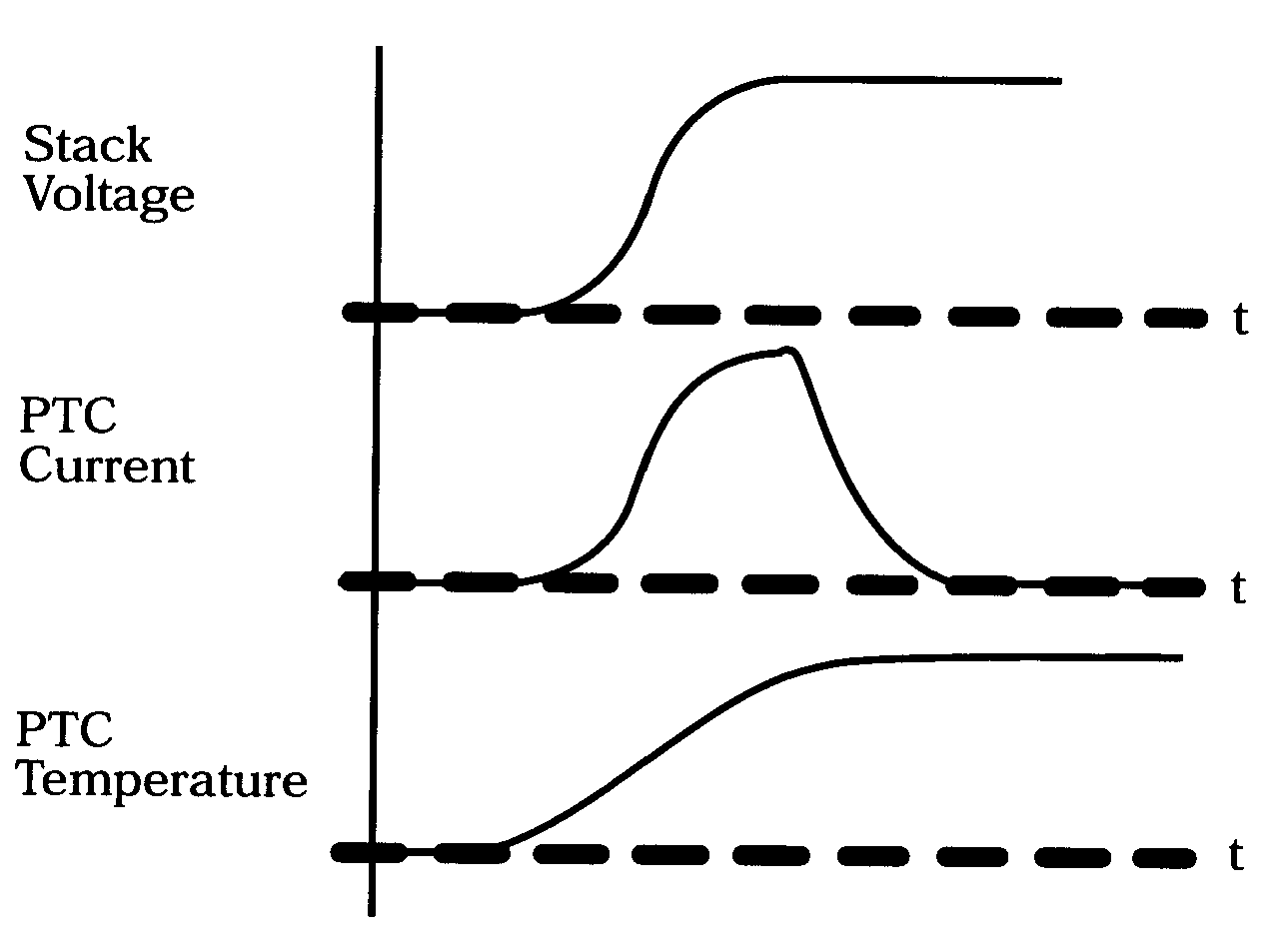
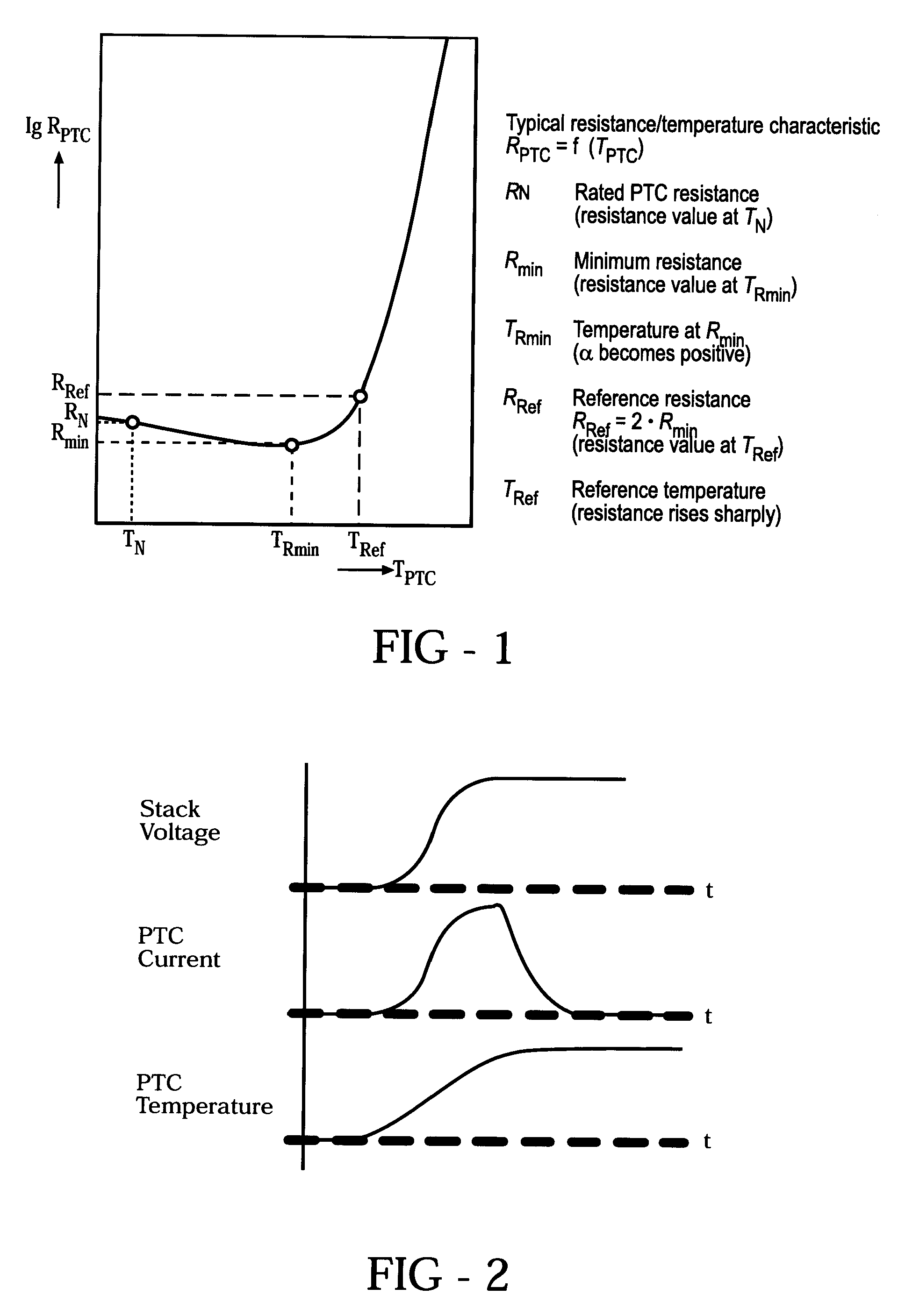
The invention is about how to regulate a fuel cell to keep it running at a low voltage level. The solution is to use a positive temperature coefficient (PTC) element as a shorting resistor. This element has low resistance at low temperatures and high resistance at normal temperatures. By using the PTC, the fuel cell can be held at a low voltage during startup, which helps protect the catalyst layer and extend the life of the fuel cell. The invention can be applied to fuel cell assemblies with plates and membranes, or with bipolar plates and membranes. The technical effect of the invention is to limit the voltage generated by the fuel cell until it reaches a normal operating temperature, which can protect the fuel cell and improve its performance.

Problems solved by technology

The MEA can be damaged by the simultaneous presence of air and hydrogen in the anode.
The amount of damage is determined by the cell voltage with higher voltages leading to greater damage.

Method used


Image

  • PTC element as a self regulating start resistor for a fuel cell stack
  • PTC element as a self regulating start resistor for a fuel cell stack
  • PTC element as a self regulating start resistor for a fuel cell stack

Examples


first embodiment

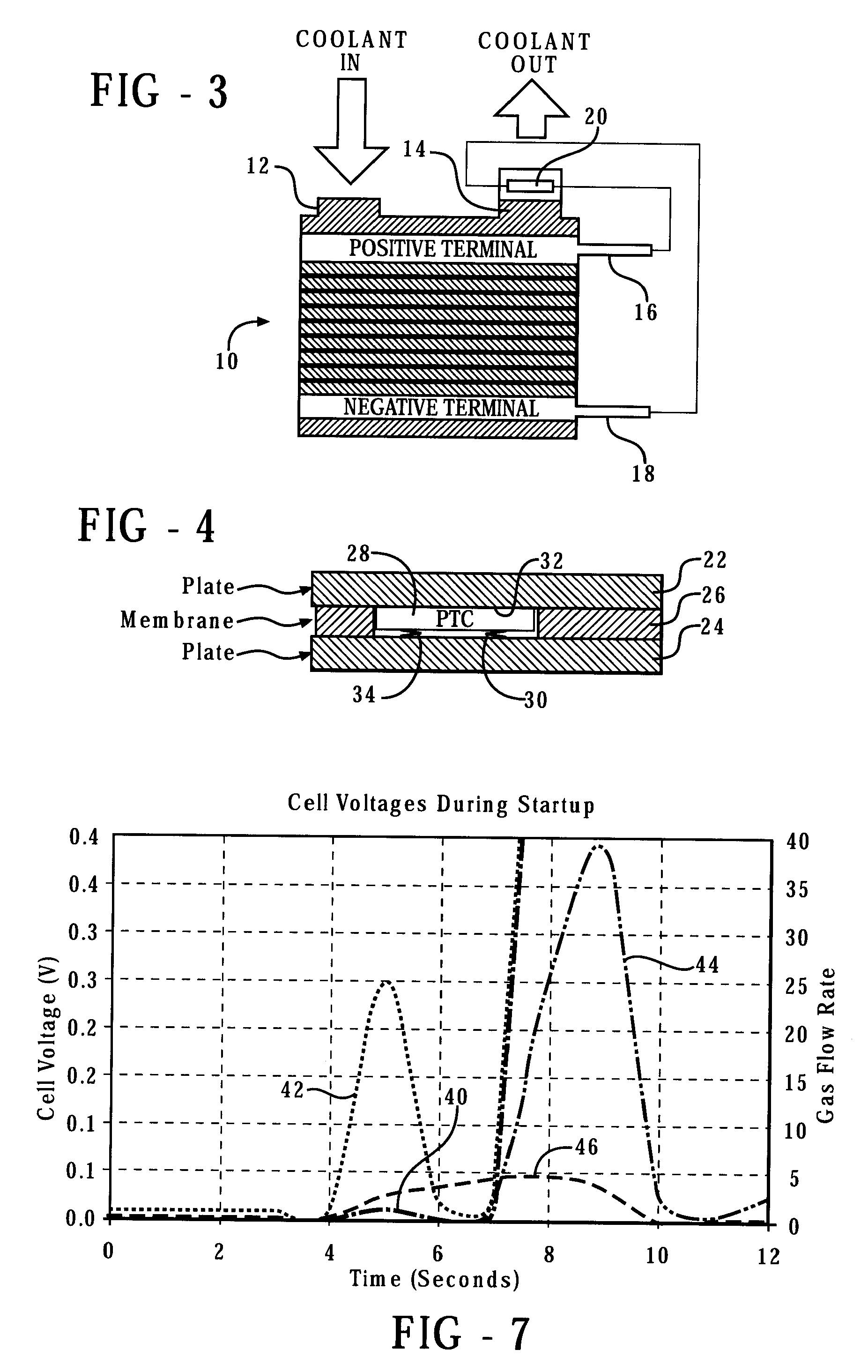
[0025]In the present invention, only one PTC element with a heat sink or coupled to the stack (e.g. coolant outlet) will be connected to a stack. In FIG. 3, a fuel cell stack has a coolant inlet 12 and a coolant outlet 14. Electrical power is generated to a load (not shown) connected between a positive terminal 16 and a negative terminal 18. A PTC element 20 is positioned at the coolant outlet 14 and is connected between the terminals 16 and 18. This element 20 would need to be designed for high voltage (up to 450 VDC) requiring a thicker PTC element to avoid shorting at the high voltage and a large contact area to get the “on” resistance down to levels where it will discharge the stack 10 in a reasonable time. The PTC element 20 is connected electrically across the entire stack and coupled thermally to the coolant outlet 14. The amount of time that the PTC element will remain in the low resistance mode is determined by the combination of its power dissipation and the heat transfer ...

second embodiment

[0026]Thin PTC elements could be integrated in every bipolar plate or membrane in the present invention. As shown in FIG. 4, plates 22 and 24 are positioned on opposite sides of a membrane 26. A PTC element 28 is positioned in a cavity 30 formed in the membrane 26. Screen printed PTC ink could be an option as well as long as it exhibits the same temperature / resistivity characteristics as shown above in FIG. 1. In a stamped design, the preferred location for the one per cell PTC element is near the coolant inlet header. This region has no reactant or coolant contact, yet is well coupled thermally to the coolant. The seal load from the neighboring cells will provide a contact force that is relatively insensitive to tolerances.

[0027]In FIG. 4, the PTC element 28 is bonded at 32 to the upper plate 22. A leaf spring 34 is positioned between the PTC element 28 and the lower plate 24 to enhance electrical contact.

[0028]FIG. 5 shows the embedded PTC element embodiment in more detail. The lo...


PUM

PropertyMeasurementUnit
contact areaaaaaaaaaaa
thickaaaaaaaaaa
resistanceaaaaaaaaaa

Abstract

At least one positive temperature coefficient element is used to efficiently control fuel cell voltage at startup and shutdown making the fuel cell more efficient and protecting the electro catalyst layer.

Description

FIELD OF THE INVENTION[0001]This invention relates to the operation of fuel cells. More particularly, the invention is directed to an improved method of regulating the starting and stopping of a hydrogen fuel cell stack.BACKGROUND OF THE INVENTION[0002]With fuel cells being desired for automotive propulsion purposes, it has become important for fuel cells to achieve full power quickly. This requires a rapid increase from ambient temperature to normal operating temperature.[0003]Electrochemical fuel cells convert fuel and oxidant into electricity, a reaction product (such as water in the case of a hydrogen fueled and oxygen oxidizing fuel cell), and heat. The fuel cell typically has a membrane electrode assembly (“MEA”) separating the fuel from the oxidant. The MEA is where the reactions take place and contains the catalyst needed to accelerate the reaction.[0004]The MEA can be damaged by the simultaneous presence of air and hydrogen in the anode. The amount of damage is determined b...

Claims


Application Information

Patent Timeline
Patent Type & Authority Applications(United States)
IPC IPC(8): H01M8/04
CPCH01M8/04223Y02E60/50H01M8/0488H01M8/0432H01M8/04225
Inventor ANDREAS-SCHOTT, BENNOSKALA, GLENN W.ROCK, JEFFREY A.LAKSHMANAN, BALSUFOLEY, ROBERT S.MURPHY, MICHAEL W.
Owner GM GLOBAL TECH OPERATIONS LLC
Learn More