
Energy storage system

a technology of energy storage and energy storage, applied in the direction of energy efficient board measures, cell components, electrochemical generators, etc., can solve the problem of intermittent solar power, and achieve the effect of reducing weight, reducing system simplification, and reducing weigh

Inactive Publication Date: 2008-08-07
AEROVIRONMENT INC
View PDF8 Cites 4 Cited by
  • Summary
  • Abstract
  • Description
  • Claims
  • Application Information

AI Technical Summary

Benefits of technology

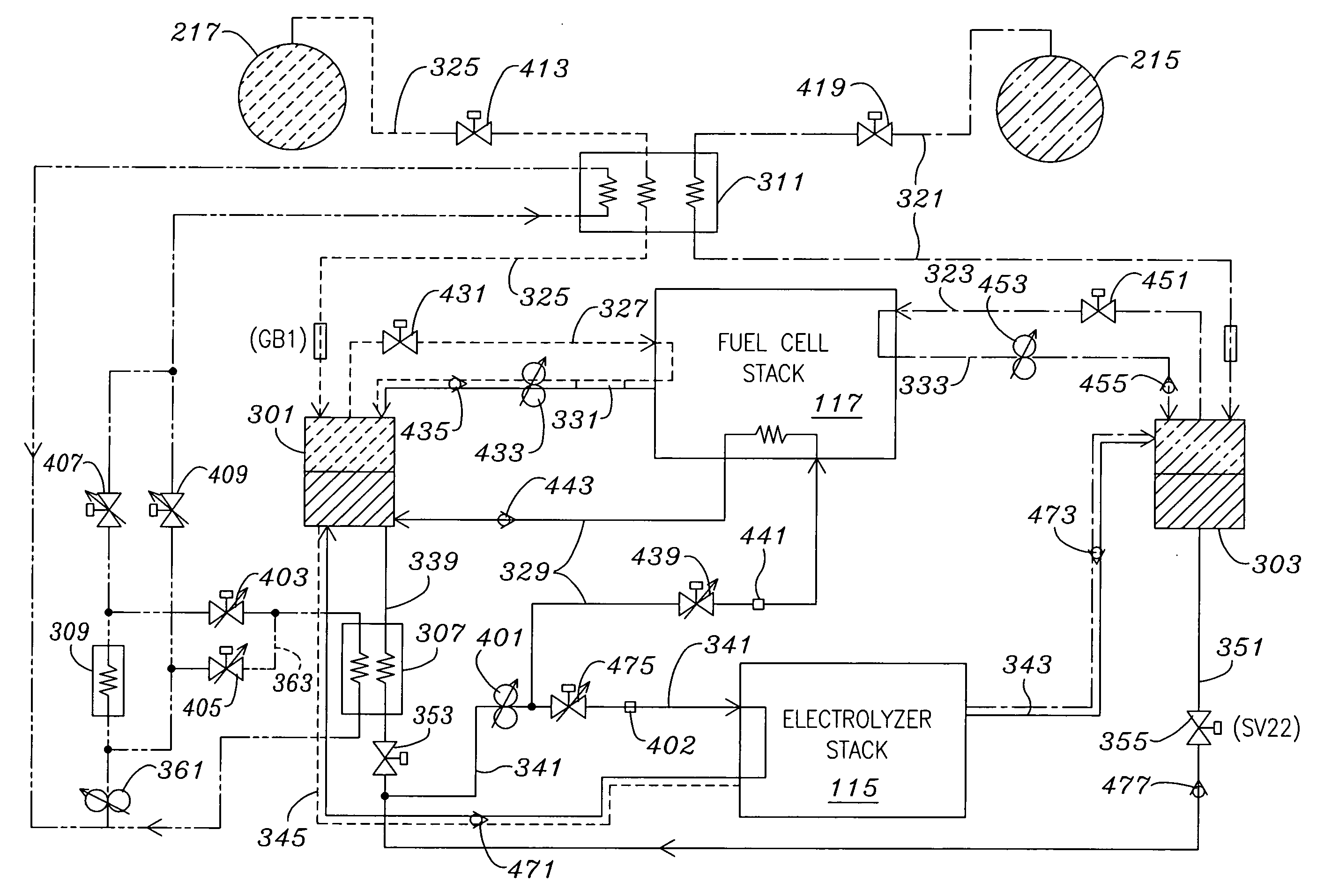
The present invention provides an energy storage system and related aircraft structures, as well as related methods. The system includes a fuel cell stack, electrolyzer stack, and heat exchanger. The heat exchanger removes excess heat from the fuel cell stack to preheat the gaseous fuel and oxidizer before they are reacted in the fuel cell stack. This feature provides for weight reduction and system simplification. The system also includes phase separators to separate gaseous reactants from liquid reaction product and store the liquid reaction product for use in the electrolyzer. The system may also include a thermal management system for the product-containing components but not for the storage tanks, which provides for cost and weight efficiency. The system storage tanks may be composed of polymer liners integral with composite shells, which provides for weight efficiency. The technical effects of the invention include weight reduction, system simplification, energy efficiency, and cost efficiency.

Problems solved by technology

However, solar power is intermittent, and solar-powered aircraft must have significant energy storage systems to store enough energy to fly through each night during a flight.

Method used


Image

  • Energy storage system
  • Energy storage system
  • Energy storage system

Examples


Embodiment Construction

[0031]The present invention provides an energy storage system. Features and advantages of the invention will become apparent from the following detailed description of the preferred embodiments, taken in conjunction with the accompanying drawings, which illustrate, by way of example, the principles of the invention.

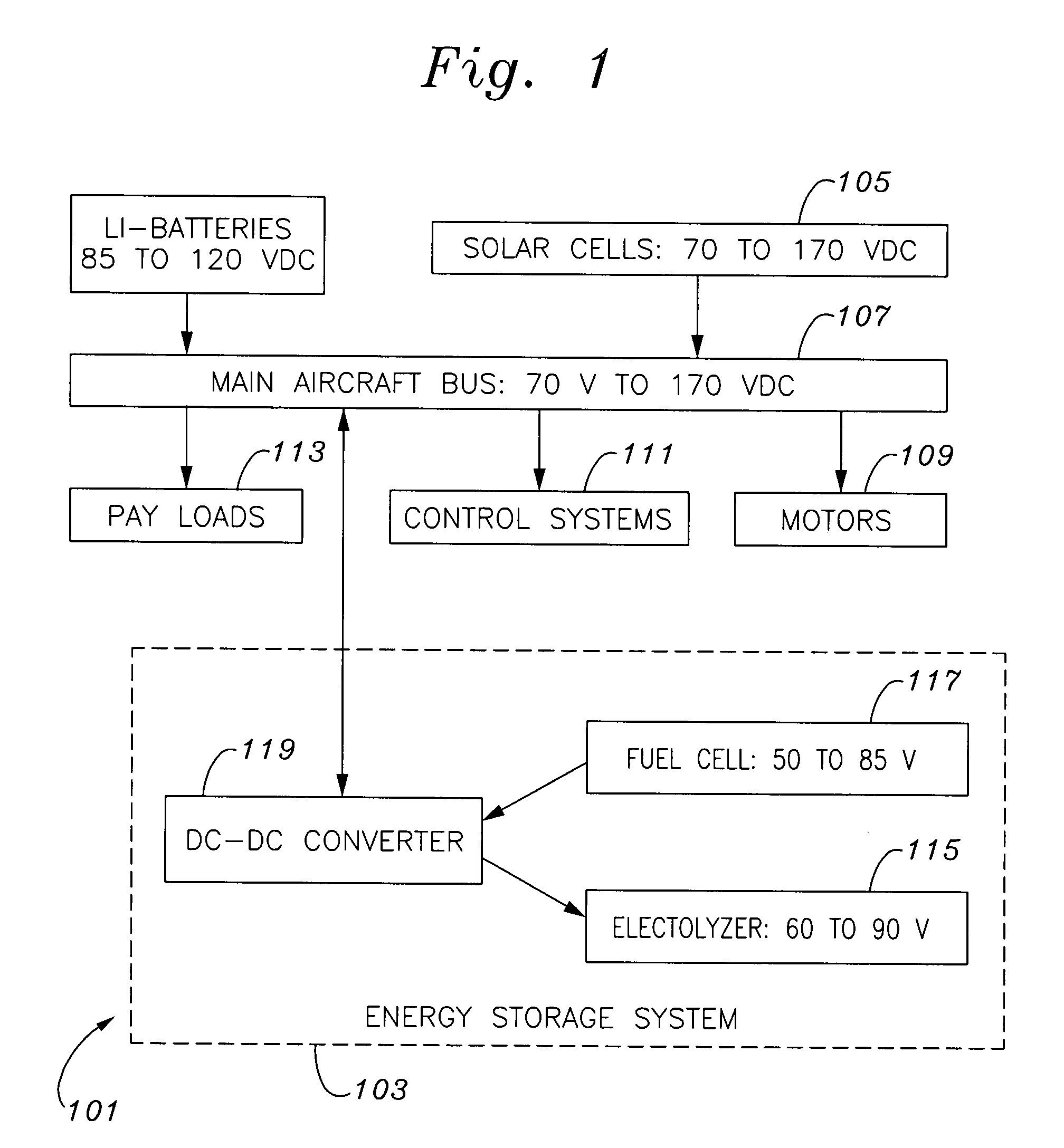
[0032]With reference to FIG. 1, a solar aircraft power system 101, including a first energy storage system 103 embodying the invention, includes solar cells 105 to provide power through a power bus 107 for aircraft motors 109 and other aircraft loads such as aircraft control systems 111 (including the energy storage system control system) and various active payloads 113. The solar cells also provide enough excess power to charge the energy storage system during the day so that the energy storage system can provide electrical energy to operate some or all of the aircraft's electrical loads when solar power is limited or not available, such as at night. Preferably, the ener...


PUM

PropertyMeasurementUnit
voltageaaaaaaaaaa
voltageaaaaaaaaaa
operating pressuresaaaaaaaaaa

Abstract

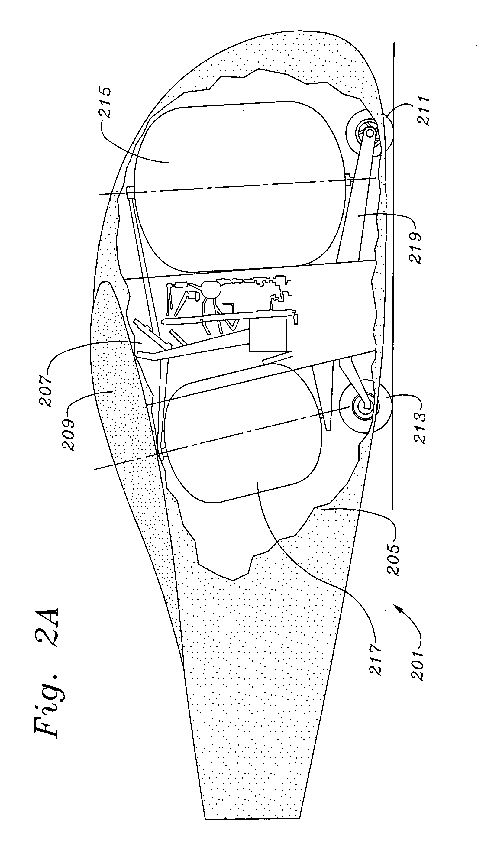
A closed loop energy storage system configured with a hydrogen tank, an oxygen tank, a fuel cell stack and an electrolyzer. A heat exchanger freeze-dries the hydrogen and oxygen prior to their storage in their respective tanks. The heat exchanger also uses excess fuel cell heat to preheat streams of hydrogen and oxygen coming from the tanks. Phase separators serve both to separate water from hydrogen and oxygen, and to store the water. A thermal management system encloses all the system components except the tanks. An airfoil-shaped shell covers the system, and the larger of the two tanks extends substantially across the shell at its point of greatest camber thickness. The tanks are composed of polymer liners integral with composite shells.

Description

BACKGROUND[0001]This application is a divisional application of application Ser. No. 10 / 418,737, filed Apr. 17, 2003, which claims priority from U.S. provisional patent application 60 / 373,301, filed Apr. 17, 2002, both of which are incorporated herein by reference for all purposes.[0002]This invention relates generally to methods and apparatus for storing energy and, more particularly, to energy storage systems for high-altitude, light weight, long duration solar powered aircraft, and related methods.[0003]Aircraft are used in a wide variety of applications, including travel, transportation, fire fighting, surveillance and combat. Various aircraft have been designed to fill the wide array of functional roles defined by these applications. Included among these aircraft are balloons, dirigibles, traditional fixed wing aircraft, flying wings and helicopters.[0004]One functional role that a few aircraft have been designed to fill is that of a tightly stationed (i.e., maintained in a sma...

Claims


Application Information

Patent Timeline
Patent Type & Authority Applications(United States)
IPC IPC(8): H01M8/04B64C3/14B64D27/02C25B1/00C25B1/04H01M8/00H01M8/02H01M8/06H01M8/18
CPCB64C2201/042Y02T90/36B64D2041/005B64D2211/00H01M8/04097H01M8/04164H01M8/04373H01M8/04768H01M8/0656H01M8/186Y02E60/368Y02E60/528Y02T50/44Y02T50/62Y02T50/69B64D27/24Y02E60/36Y02E60/50Y02P20/133Y02T50/50Y02T50/40Y02T50/60Y02T90/40B64D27/353
Inventor HIBBS, BART D.PARKS, WILLIAM M.VELEV, OMOURTAG A.
Owner AEROVIRONMENT INC
Learn More