Rotary Vector Gear for Use in Rotary Steerable Tools

a rotary vector and tool technology, applied in mechanical equipment, couplings, directional drilling, etc., can solve problems such as safety compromise, all prior art tools must be withdrawn, and bit-walk becomes a major problem

Inactive Publication Date: 2008-08-14
HALLIBURTON ENERGY SERVICES INC
View PDF3 Cites 25 Cited by
  • Summary
  • Abstract
  • Description
  • Claims
  • Application Information

AI Technical Summary

Benefits of technology

[0022]The cycloid device may be used as a single unit or a dual unit within a rotary steerable tool (although options involving a plurality of devices within an assembly can be envisioned) to provide bit point of bit push. If a single unit is utilized the cycloid system will provide bit point offset vector steering within the wellbore; whereas, a dual cycloid system will provide bit push offset vector steering within the wellbore. The use of cycloid devices within downhole steering tools allows the operator to vary the dog-leg severity (or magnitude of wellbore curvature) during the drilling operation; whereas, current steering tools have fixed dog-leg severity which can only be varied when the steering tool is brought to the surface.
[0024]In the preferred mode, when used in a rotary steerable tool, the device can control the wellbore path. Sensors may be mounted in the cycloid device or within the housing of the rotary steerable tool that provide wellbore path reference data (I.e., up / down, north / south, east / west, plus other required geophysical data). This data may then be linked through the control system to provide real-time adjustments to the cycloid gear thereby controlling the wellbore path. A communication link may be established with a communication protocol that will allow real-time communication between the rotary steerable tool and the surface thereby providing further wellbore path control and control of the dog-leg severity of the wellbore path.

Problems solved by technology

However, in a highly inclined or horizontal well, bit-walk becomes a major problem.
However, if changes in the forces that cause bit-walk occur while drilling, all the prior art tools must be withdrawn in order to correct the direction of the wellbore.
This results in a compromise of safety and a large expenditure of time and money.

Method used


Image

  • Rotary Vector Gear for Use in Rotary Steerable Tools
  • Rotary Vector Gear for Use in Rotary Steerable Tools
  • Rotary Vector Gear for Use in Rotary Steerable Tools

Examples


Embodiment Construction

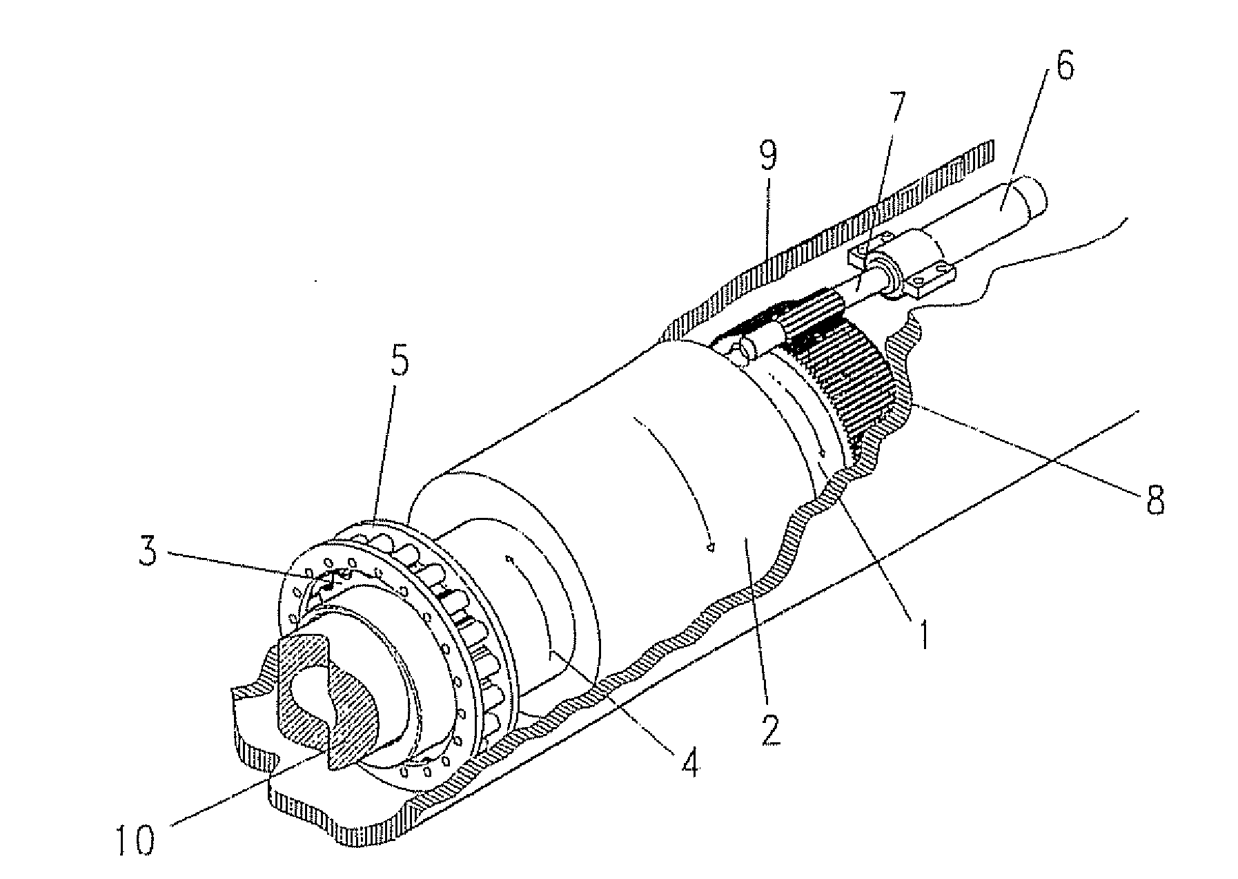
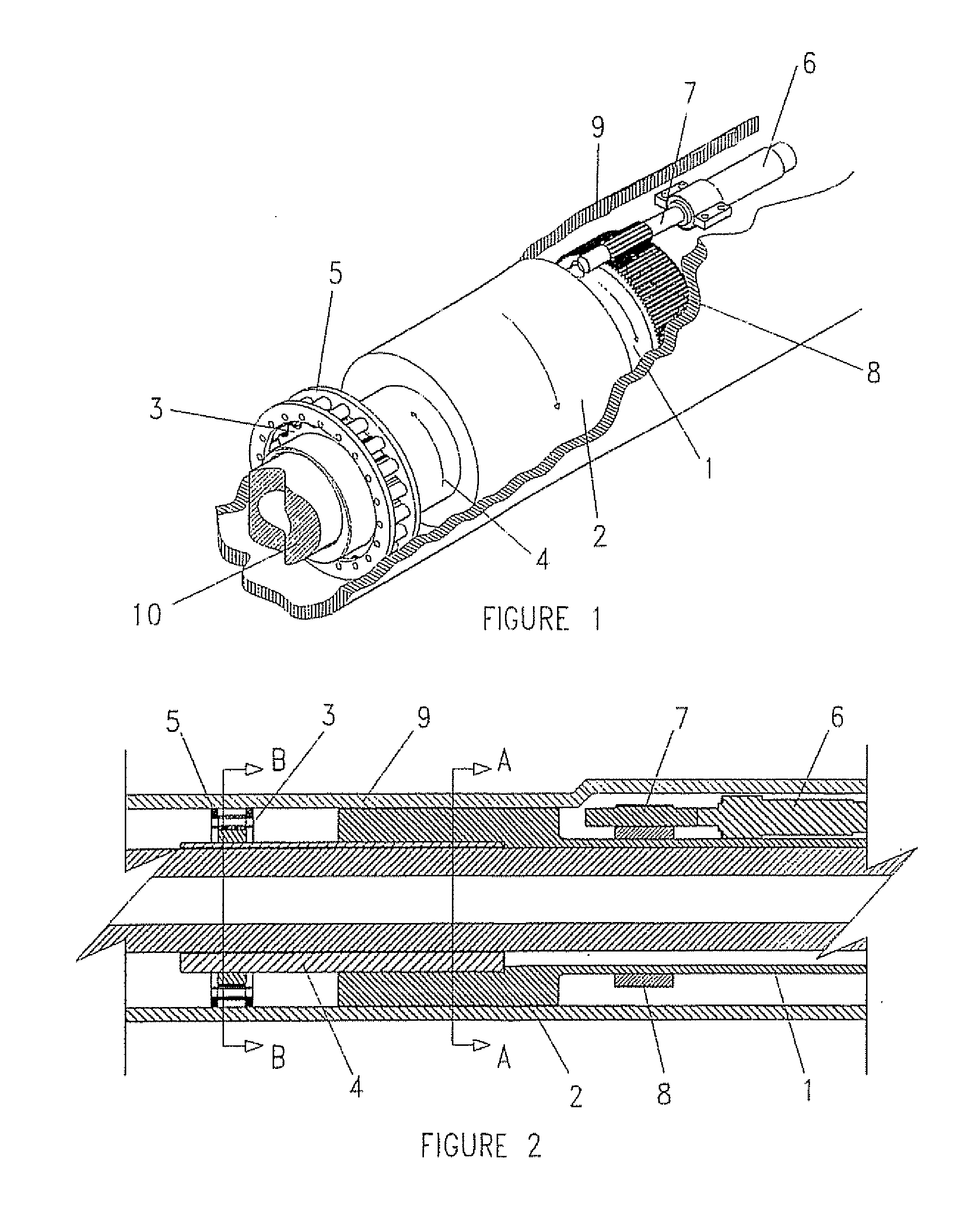
[0036]The system will be described assuming that it will be used in a downhole rotary steering tool; however, it should be understood that the cycloid drive system may be used in other apparatuses to provide progressive control of the offset of the longitudinal axis. The cycloid or rotary vector gear system is enclosed in an outer housing that is approximately 12 feet in length that is made up from seven pinned or threaded section sections. The total length of the tool is approximately 16 feet. FIG. 5 shows the cycloid system contained within a rotary steerable tool that utilizes an offset outer housing to interact with the wall of the wellbore thereby providing the fulcrum for bit vectoring.

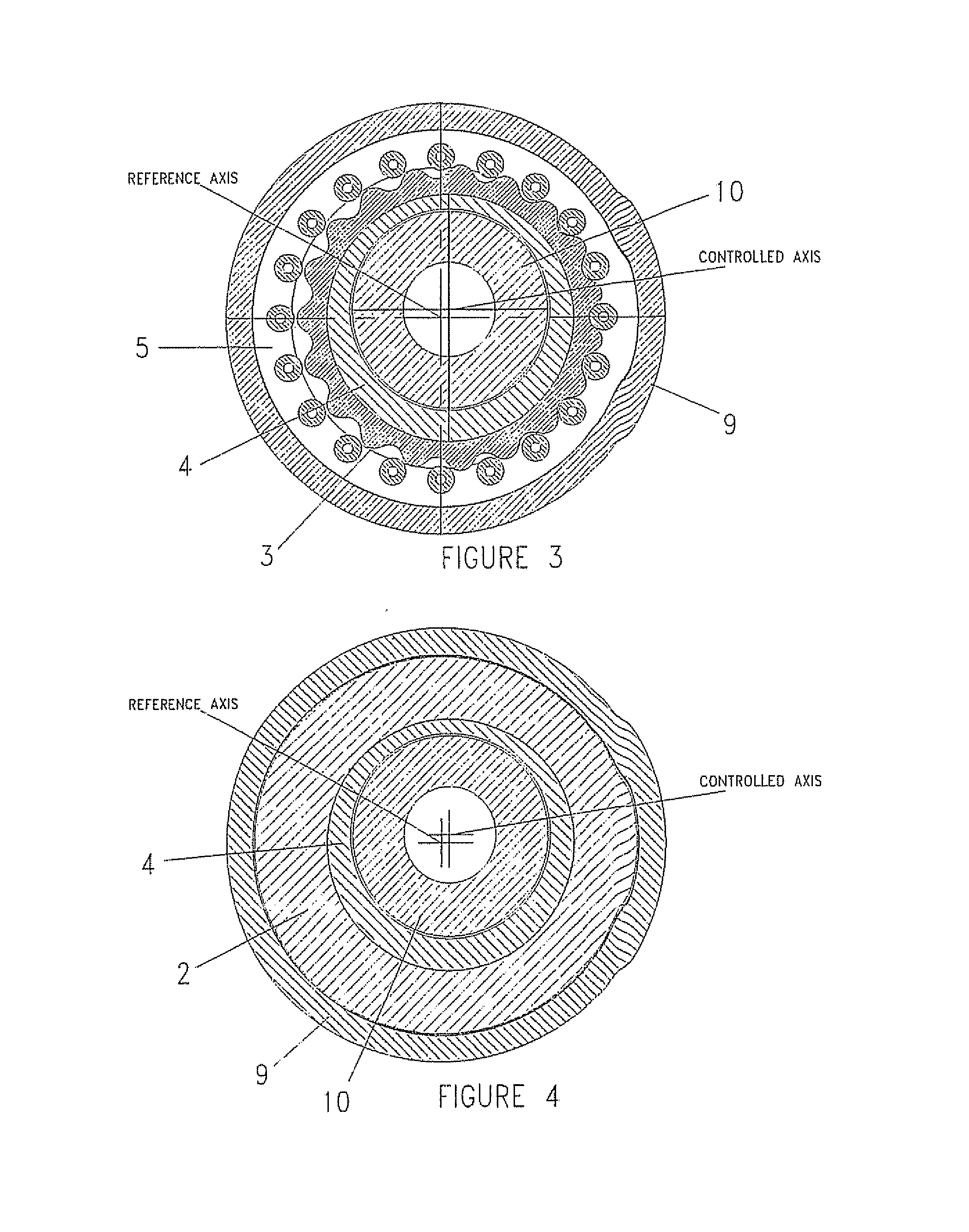
[0037]Referring now to FIGS. 1-4, the cycloid device consists of six major components:[0038]a Concentric Input Sleeve, 1, or Rotary Sleeve,[0039]a First Stage Eccentric Sleeve, 2, that is joined to the input sleeve, 1, and is sometimes referred to as the Inner Sleeve),[0040]an External Tooth Cyc...


PUM


Abstract

A rotary vector gear for controlling longitudinal axis offset about a central longitudinal axis is disclosed. The device uses single rotary motion through a rotary vector gear to produce hypotrochoidic offset similar to a flower petal and is capable or ready return to zero offset. The device may be used in downhole rotary steerable oil and gas drilling tools and in computer controlled milling machines for providing controlled offset.

Description

TECHNICAL FIELD OF THE INVENTION[0001]The present invention relates to the field of oil and gas drilling. More specifically the present invention relates to an apparatus and method for selecting or controlling, from the surface, the direction in which a wellbore proceeds.BACKGROUND OF THE INVENTION[0002]A drill operator often wishes to deviate a wellbore or control its direction to a given point within a producing formation. This operation is known as directional drilling. One example of this is for a water, injection well in an oil field, which is generally positioned at the edges of thee field and at a low point in that field (or formation).[0003]In addition to controlling the required drilling direction, the formation through which a wellbore is drilled exerts a variable force on the drill string at all times. Tins along with the particular configuration of the drill can cause the drill bit to wander up, down, right or left. The industrial term given to this effect is “bit-walk” ...

Claims


Application Information

Patent Timeline
Patent Type & Authority Applications(United States)
IPC IPC(8): E21B7/08E21B7/06
CPCE21B7/067E21B7/06
Inventor EARLES, RONALD G.LASATER, JEFFREY B.
Owner HALLIBURTON ENERGY SERVICES INC
Why Eureka
Try Eureka