Method For Machining Workpieces By Using Laser Radiation

a technology of laser radiation and workpieces, applied in the direction of laser beam welding apparatus, welding/soldering/cutting articles, manufacturing tools, etc., can solve the problems of increased cutting waste, increased cost of plant engineering (stamping tools and detectors), and inability to optimize the machining speed in the direction of shorter machining times

Inactive Publication Date: 2008-08-14
FRAUNHOFER GESELLSCHAFT ZUR FOERDERUNG DER ANGEWANDTEN FORSCHUNG EV
View PDF8 Cites 5 Cited by
  • Summary
  • Abstract
  • Description
  • Claims
  • Application Information

AI Technical Summary

Benefits of technology

[0007]It is therefore the object of the invention to provide a method for the machining of moved workpieces by using laser radiation with which

Problems solved by technology

Such markings are, however, disadvantageous since they have to be formed additionally, which increases the cost for the plant engineering (stamping tools and detectors).
Bending or folding edges, howe

Method used


Image

  • Method For Machining Workpieces By Using Laser Radiation
  • Method For Machining Workpieces By Using Laser Radiation

Examples


Embodiment Construction

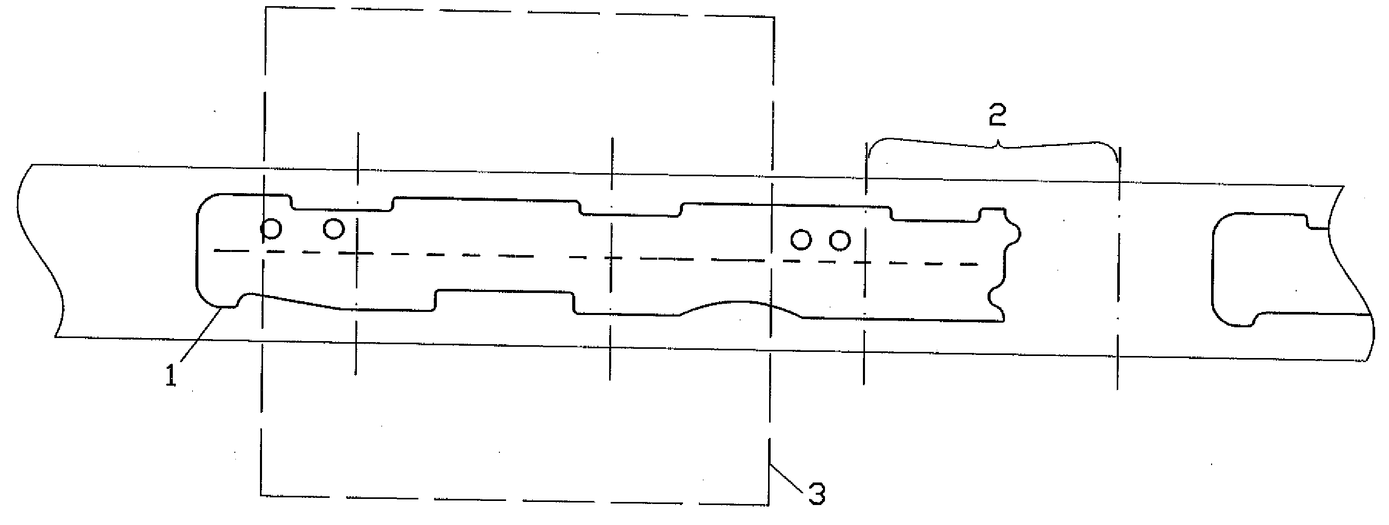
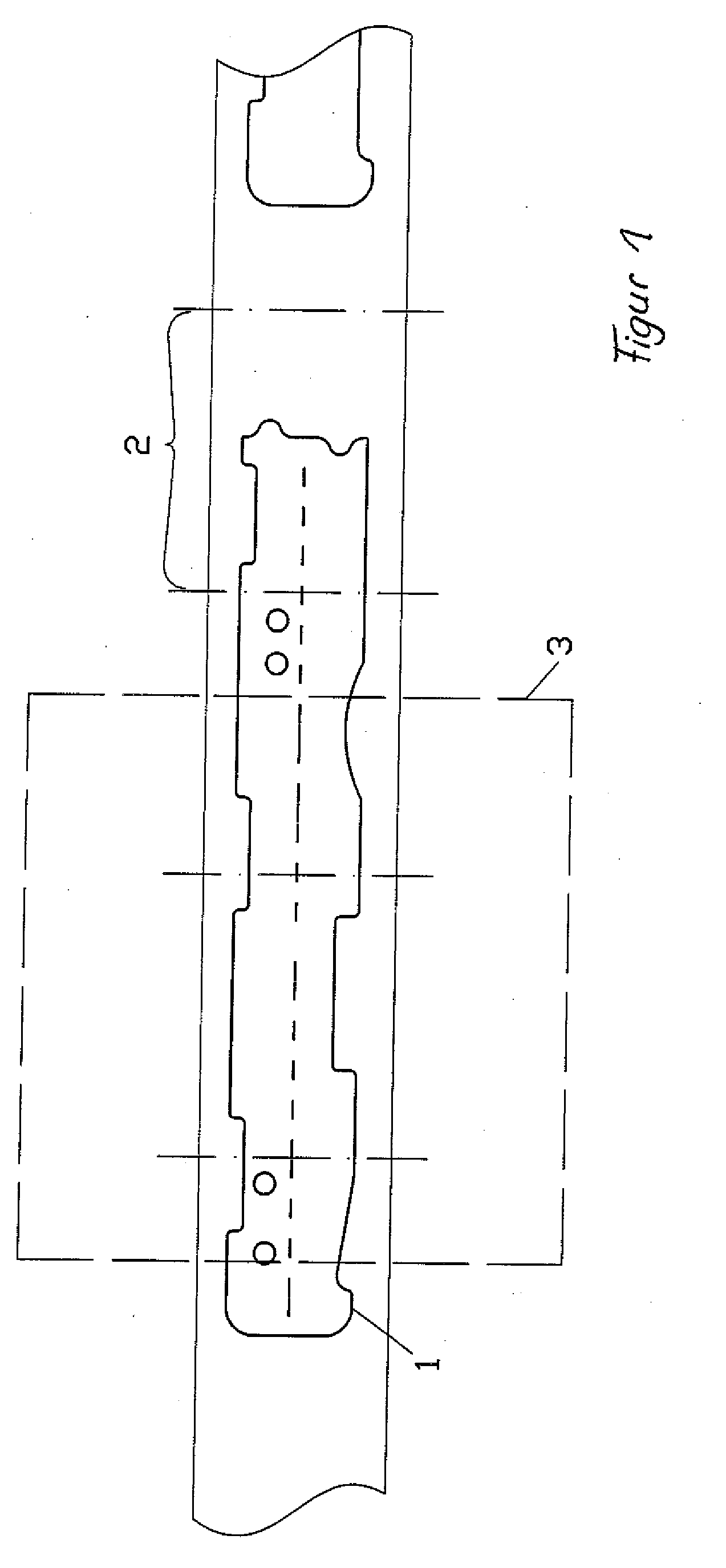
[0036]A machining on a plastic foil moved in a translatory manner as a workpiece 1 should be carried out using a laser beam with the method in accordance with the invention. The plastic foil can be clamped between two rollers, not shown here, and can be transported in a longitudinal direction, and a feed can thus be realized, by rolling up and down.

[0037]In this connection, the plastic film should be cut in a special shape with a predetermined marginal contour (solid line) using a laser beam which is two-dimensionally deflectable. A perforation (dashed line) should moreover be formed parallel to the feed direction. This can be achieved by a slight material removal, starting from the surface of the plastic foil.

[0038]The positional coordinates for the outer marginal contour and perforation were supplied in advance to an electronic evaluation and control unit and form the basis for the machining contour.

[0039]Such positional coordinates were associated with virtual machining segments ...


PUM

PropertyMeasurementUnit
Fractionaaaaaaaaaa
Lengthaaaaaaaaaa
Poweraaaaaaaaaa

Abstract

The invention relates to a method for machining workpieces by using laser radiation, wherein the workpieces to be machined are moved during the machining and at least one laser beam is deflected with respect to two axes aligned orthogonally to one another. It is therefore the object of the invention to form large-area machining contours with as high a machining speed and as great an accuracy as possible. In the method in accordance with the invention, a procedure is followed that a laser beam is deflected within a working field with respect to two axes aligned orthogonally to one another. Positional coordinates of the respective machining contour are moreover associated in an electronic evaluation and control unit with virtual machining segments in which the machining is carried out sequentially. The borders of individual machining segments are predetermined so that the maximum spacing of mutually oppositely disposed borders of the respective machining segments does not exceed 50% of the maximum length of the working field for the laser beam in the feed direction of the moved workpiece.

Description

BACKGROUND[0001]The invention relates to a method for machining workpieces by using laser radiation, wherein the workpieces to be machined are moved during the machining and at least one laser beam is deflected with respect to two axes aligned orthogonally to one another. High machining speeds and a corresponding machining accuracy can be achieved with the invention without the costs for the required plant engineering being increased with respect to conventional solutions. An automated movement contour programming is also possible.[0002]The most varied contours can be machined which should also be formed on the workpiece in the form of irregular patterns or patterns which do not repeat. The machining contours can be dimensioned very large and can be substantially larger than a working field of a laser beam which can be deflected two-dimensionally by means of scanner mirrors.[0003]Different types of machining such as cutting processes, stock removal processes, structuring processes, ...

Claims


Application Information

Patent Timeline
IPC IPC(8): B23K26/08
CPCB23K26/0823B23K26/0838B23K2201/16B23K26/4065B23K26/0846B23K2101/16B23K2103/42B23K2103/50
Inventor KLOTZBACH, ANNETTFLEISCHER, VEIKOMORGENTHAL, LOTHAR
Owner FRAUNHOFER GESELLSCHAFT ZUR FOERDERUNG DER ANGEWANDTEN FORSCHUNG EV
Why Eureka
Try Eureka