Capacitive sensor

a capacitive sensor and sensor technology, applied in capacitance measurement, resistance/reactance/impedence, instruments, etc., can solve the problems of amplitude fluctuations, labor-intensive and costly circuit engineering, and the inability to compare the difference of current-voltage-convertible currents,

Inactive Publication Date: 2008-08-14
IMF ELECTRONIC GMBH
View PDF5 Cites 5 Cited by
  • Summary
  • Abstract
  • Description
  • Claims
  • Application Information

AI Technical Summary

Benefits of technology

[0012]The object of this invention is to avoid—at least partially—the indic

Problems solved by technology

The disadvantage to the above-described capacitive sensor is that the analysis of the current signals in the analysis unit is comparatively expensive.
In particular, the presetting of a reference value, to which the difference of the current-voltage-converted currents is compared, is labor-intensive and costly in terms of circuit engineering, and in addition, is prone to frequency and amplitude fluctuations of the alternating signal.
Furthermore, it has been found that the known sensors in the working frequency of 2 MHz indicated in the prior art are not suitable to be used as fill-level sensors, since they are not able to distinguish whether a

Method used


Image

  • Capacitive sensor
  • Capacitive sensor
  • Capacitive sensor

Examples


Embodiment Construction

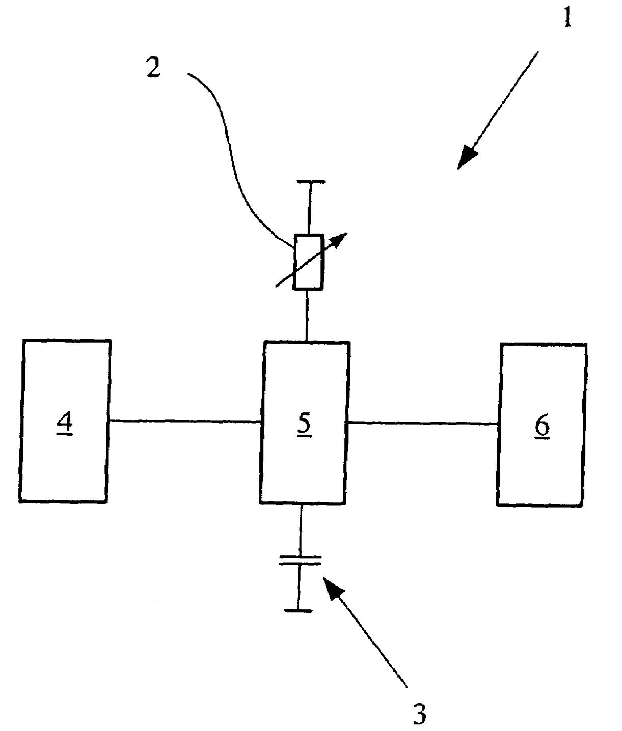
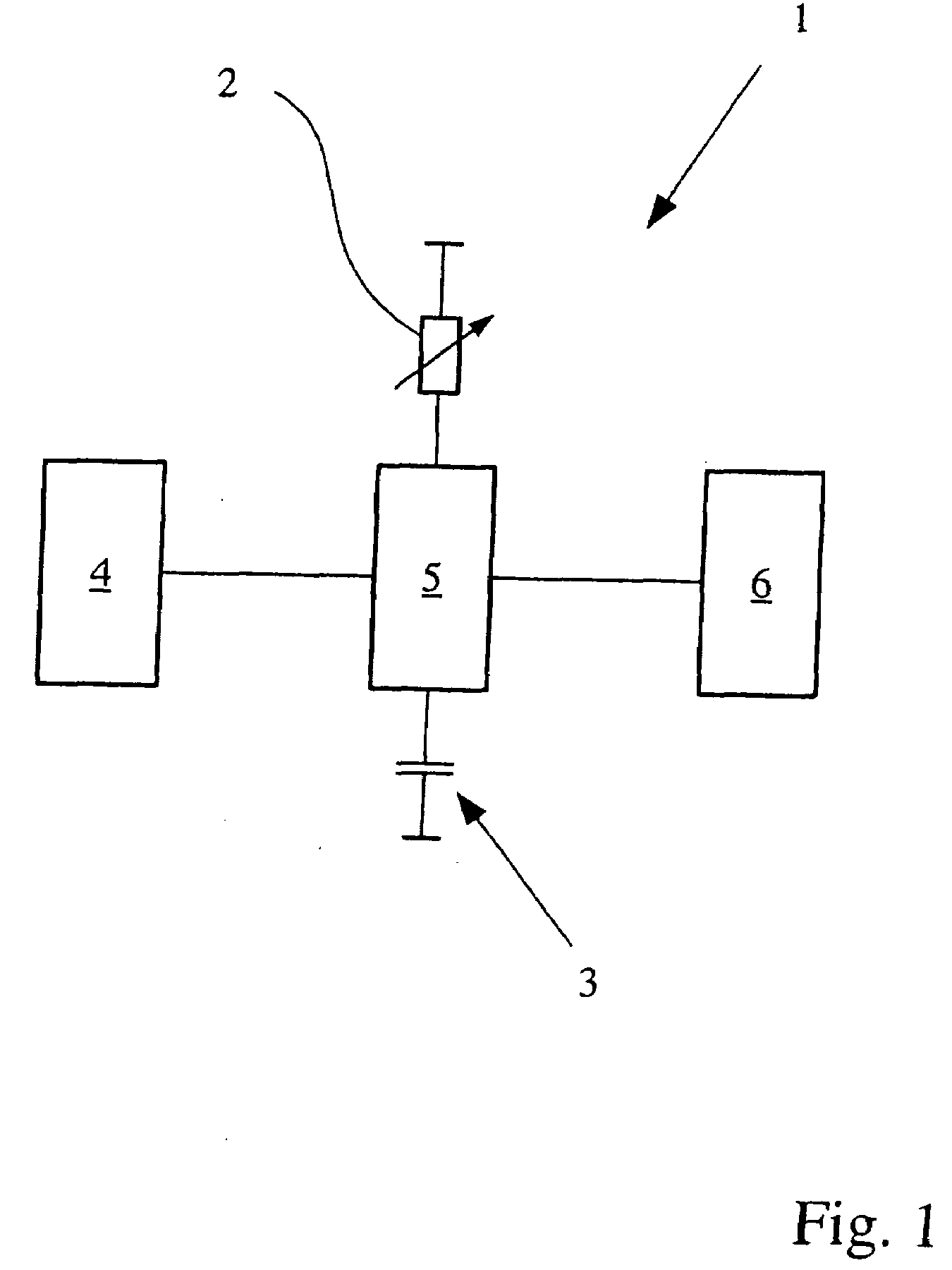
[0058]FIG. 1 shows a first embodiment of a capacitive sensor 1 with a reference impedance 2 and a measuring condenser 3, at least one electrical alternating signal source 4, and a current supply network 5 as well as with an analysis unit 6. The reference impedance 2 and the measuring condenser 3 are connected, via the current supply network 5, with the alternating signal source 4 and the analysis unit 6 in such a way that the charge and discharge currents of the reference impedance 2 and the measuring condenser 3 and / or an analysis signal from the analysis unit 6 that characterizes the charge and discharge currents of the reference impedance 2 and the measuring condenser 3 can be analyzed, whereby the reference impedance 2 can be tuned. By the ability of the reference impedance 2 to be tuned, the value of the reference impedance in each desired state of influence of the capacitive sensor can be adjusted to the impedance or capacitance of the measuring condenser that is dependent on ...


PUM


Abstract

A capacitive sensor with at least one reference impedance (2) and at least one measuring condenser (3), at least one electrical alternating signal source (4), a current supply network (5) and an analysis unit (6) in which the reference impedance (2) and the measuring condenser (3) are connected via the current supply network (5) to the alternating signal source (4) and the analysis unit (6) in such a way that the charge and discharge currents of the reference impedance (2) and the measuring condenser (3) and/or an analysis signal from the analysis unit (6) that characterizes the charge and discharge currents of the reference impedance (2) and the measuring condenser (3) can be analyzed. As a result, the reference impedance (2) can be tuned. The capacitive sensor avoids—at least partially—drawbacks in the capacitive sensors known from the prior art in that the reference impedance can be tuned.

Description

BACKGROUND OF THE INVENTION[0001]1. Field of Invention[0002]The invention relates to a capacitive sensor with at least one reference impedance and at least one measuring condenser, with at least one electrical alternating signal source, with a current supply network, as well as with an analysis unit, whereby the reference impedance and the measuring condenser are connected via the current supply network to the alternating signal source and the analysis unit such that the charge and discharge currents of the reference impedance and the measuring condenser can be analyzed by the analysis unit.[0003]2. Description of Related Art[0004]Capacitive sensors of the initially mentioned type are known from, for example, the U.S. Pat. Nos. 5,650,730 and 5,793,217 and are used for determining the capacitance of the measuring condenser or the change in the capacitance of the measuring condenser. These sensors have a special current supply network, namely such a one that consists of diodes, connec...

Claims


Application Information

Patent Timeline
IPC IPC(8): G01R27/26
CPCG01R27/2605G01D5/24
Inventor GUNDLACH, JOCHENPALATA, JAROMIR
Owner IMF ELECTRONIC GMBH
Why Eureka
Try Eureka