
Control channel signaling in a multiple access wireless communication system

a wireless communication system and control channel technology, applied in the field of wireless communication systems, can solve the problems of large computation resources, large processing delays, and large energy requirements for transmitting tasks that must be performed by the radio, and achieve the effect of reducing power consumption for users

Inactive Publication Date: 2008-08-14
COMSYS COMM & SIGNAL PROC
View PDF19 Cites 88 Cited by
  • Summary
  • Abstract
  • Description
  • Claims
  • Application Information

AI Technical Summary

Benefits of technology

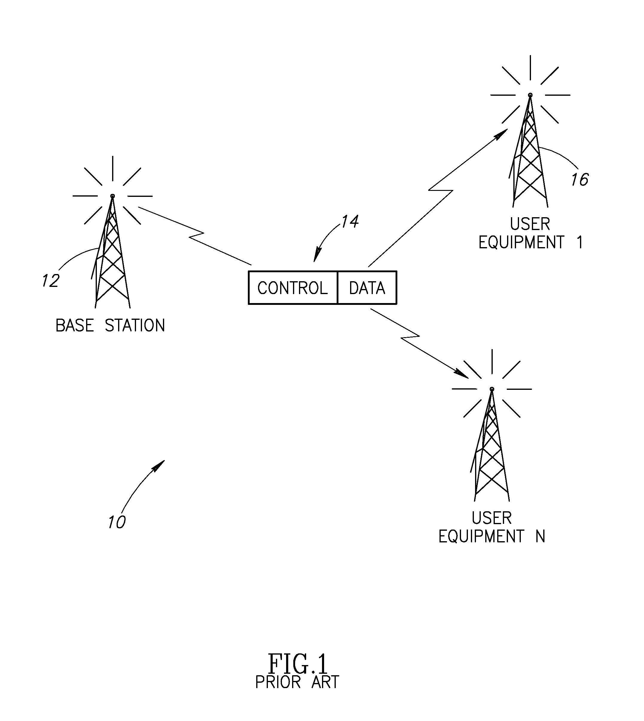
[0031]Accordingly, the present invention provides a novel and useful method and system for control channel signaling for use in multiple access wireless communication systems. The control channel signaling mechanism of the present invention is operative to reduce power consumption for users that are not served in a current frame. This is achieved by minimizing the number of OFDMA symbols that UEs not served in a current frame are still required to receive, decode and interpret. Only UEs served in the current frame are required to receive, decode and interpret the entire control channel message.
[0032]In the mechanism of the present invention, a user receives and decodes only a first portion of the control channel signaling which contains a list of u-IDs served in that particular frame. This list is typically transmitted in one or two OFDM symbols at the earliest part of the frame. If a user's u-ID does not appear in the list, it may shut off its associated receiver circuitry and keep its transmitter circuitry off as well until the following frame. This provides a significant benefit in terms of ‘stand-by time’ (or ‘hold time’) and ‘on time’ (or ‘talk time’) since the ability to shut the receiver off earlier significantly reduces power consumption. All users sharing a cell transmission receive and decode the list of users (u-ID information) before continuing to receive and decode the remainder of the control channel message, which is eventually followed by data reception or transmission. It is noted that the control signaling is also used to allocate up-link (UL) resources for transmission typically in the next frame. In FDD schemes TX and RX frames are transmitted concurrently. In TDD schemes, however, they are fixed TX after RX.
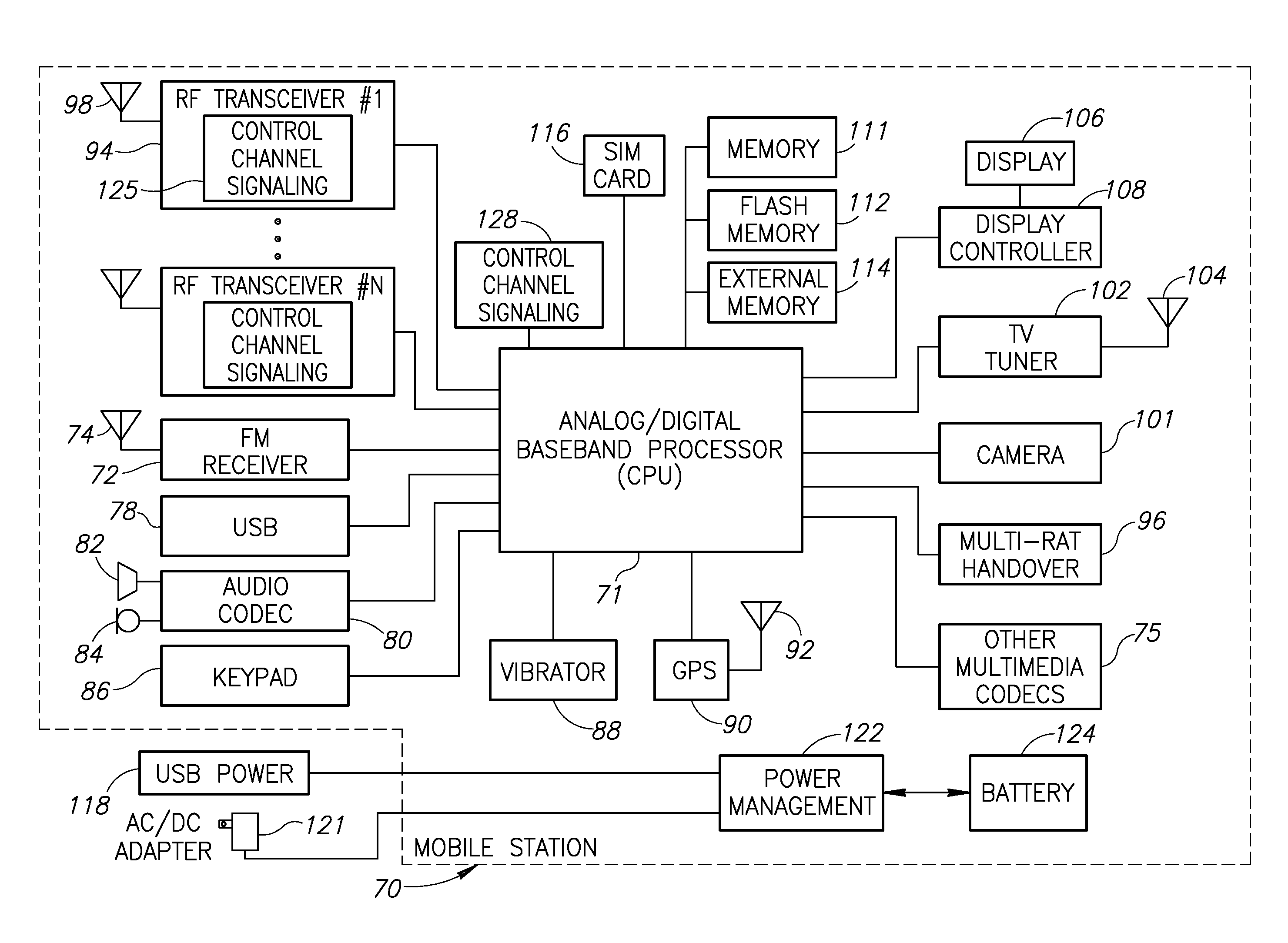
[0039]There is also provided in accordance with the invention, a radio comprising a transmitter, a receiver, a baseband processor coupled to the transmitter and the receiver and a control channel signaling unit coupled to the transmitter and operative to transmit user-ID information addressed in a current frame as a decodable entity at the beginning of the current frame thereby enabling the receiver to cease continued reception of the current frame if its respective user-ID has no corresponding assignment therein.

Problems solved by technology

Moreover, the tasks that must be performed by the radio to transmit and receive are typically very complex and require large amounts of computation resources.
This typically results in processing delays and the requirement of relatively large amounts of energy to transmit and receive a symbol.
This results in increased operation time for the receiver which causes a significant increase in power consumption and consequent reduction in receiver standby time.
This is a major concern particularly for mobile receivers but may also affect fixed receivers located in the base stations.
This mode of operation is permitted but is very inefficient from the network perspective since the control signaling overhead is considerably high and network efficiency is greatly reduced.
Reception of the entire control message, however, is still unavoidable.

Method used


Image

  • Control channel signaling in a multiple access wireless communication system
  • Control channel signaling in a multiple access wireless communication system
  • Control channel signaling in a multiple access wireless communication system

Examples


Embodiment Construction

Notation Used Throughout

[0055]The following notation is used throughout this document.

TermDefinitionAAAAuthentication Authorization and AccountingACAlternating CurrentADCAnalog to Digital ConverterARQAutomatic Repeat RequestASICApplication Specific Integrated CircuitAVIAudio Video InterfaceBMPWindows BitmapBWABroadband Wireless AccessCDMACode Division Multiple AccessCPCyclic PrefixCPUCentral Processing UnitDACDigital to analog ConverterDCDirect CurrentDLDownlinkDRAMDynamic Random Access MemoryDVBDigital Video BroadcastECCError Correction CodeEDGEEnhanced Data rates for GSM EvolutionEEPROMElectrically Erasable Programmable Read Only MemoryEPROMErasable Programmable Read Only MemoryEVDOEvolution-Data OptimizedFDDFrequency Division DuplexFECForward Error CorrectionFEMFront End ModuleFFTFast Fourier TransformFMFrequency ModulationFPGAField Programmable Gate ArrayGPRSGeneral Packet Radio ServiceGPSGlobal Positioning SatelliteGSMGlobal System for Mobile CommunicationHARQHybrid Automatic R...


PUM


Abstract

A novel and useful method and system for control channel signaling for use in multiple access wireless communication systems. The control message portion of the frame is divided into two portions: a first portion for transmitting a list of u-ID information and a second portion for transmitting all other remaining control information. All user identification information (u-ID information) is placed at the beginning of the control portion of a frame, typically in one or two symbols sent in the earliest part of the frame. The remaining control information (i.e. resource allocation and decoding information) is sent in the second portion of the control message. Users that do not have a resource assignment in a frame can skip the remainder of the frame, including the rest of the control message and data, and shutdown their receivers thus reducing power consumption. Only those UEs served in the current frame need to continue reception and decoding of the remainder of the control message and subsequent data.

Description

REFERENCE TO PRIORITY APPLICATION[0001]This application claims priority to U.S. Provisional Application Ser. No. 60 / 889,155, filed Feb. 9, 2007, entitled “Signaling Method For Multiple Access Wireless Communication System,” incorporated herein by reference in its entirety.FIELD OF THE INVENTION[0002]The present invention relates generally to wireless communication systems and more particularly relates to a method and system of control channel signaling for use in a multiple access wireless communication system.BACKGROUND OF THE INVENTION[0003]Orthogonal Frequency Division Multiplexing (OFDM), a digital multi-carrier modulation scheme, is well known in the art. It uses a large number of closely spaced subcarriers that are orthogonal to each other. Each subcarrier is modulated with a conventional modulation scheme (e.g., quadrature amplitude modulation (QAM)) at a low symbol rate, maintaining data rates similar to conventional single carrier modulation schemes in the same bandwidth. T...

Claims


Application Information

Patent Timeline
Patent Type & Authority Applications(United States)
IPC IPC(8): H04J11/00
CPCH04L1/0025H04L1/0029H04L1/0079H04L5/0007Y02B60/50H04L5/0092H04W72/14H04W52/0216H04L5/0053Y02D30/70H04W72/23
Inventor SCHEIM, JACOBSHABTAY, OPHIR
Owner COMSYS COMM & SIGNAL PROC
Learn More