Apparatus and Methods of Determination of State of Charge in a Redox Flow Battery

a technology of redox flow and apparatus, applied in the field of measurement, can solve the problems of increasing so as to increase the photometric density of light falling, increase the signal-to-noise ratio of the photometric measurement, and increase the effect of light falling

Inactive Publication Date: 2008-08-14
IMERGY POWER SYST
View PDF79 Cites 111 Cited by
  • Summary
  • Abstract
  • Description
  • Claims
  • Application Information

AI Technical Summary

Problems solved by technology
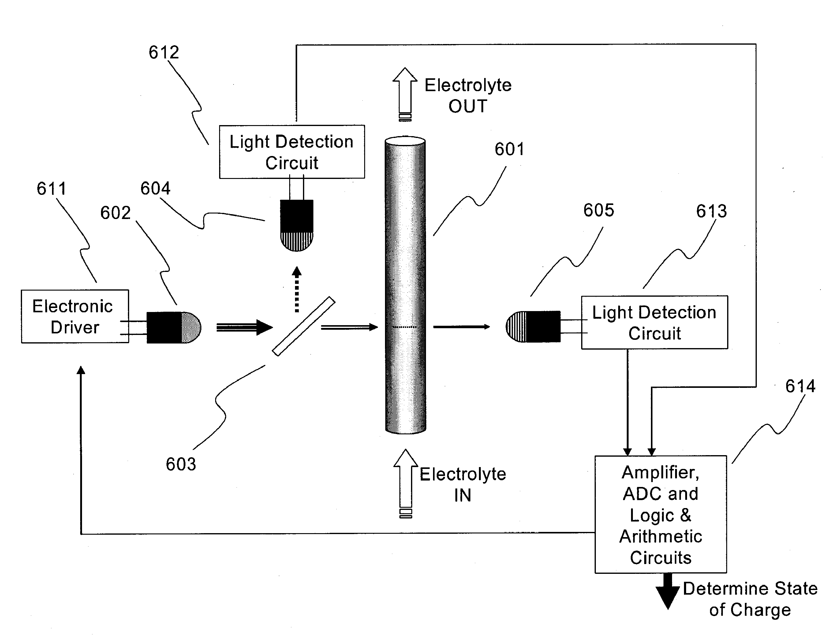
In further or additional embodiments said lensing effect increases the photometric density of light falling on the detector, resulting in an increase in the signal-to-noise ratio of the photometric measurement.

Method used


Image

  • Apparatus and Methods of Determination of State of Charge in a Redox Flow Battery
  • Apparatus and Methods of Determination of State of Charge in a Redox Flow Battery
  • Apparatus and Methods of Determination of State of Charge in a Redox Flow Battery

Examples


example 1

Preparation of Correlation Tables (Method 1)

[0124]The absorption spectra of the iron side (Catholyte) of a mixed reactant (FeCl2, FeCl3, CrCl3) half cell were determined for known states of charge / discharge (5% charged, 25% charged, 50% charged, 75% charged and 95% charged) and are shown in FIG. 4. The absorbance at 900 nm for each of the charge states was recorded as shown in the table below, and plotted to form a correlation graph as shown in FIG. 8.

%Catholyte AbsorptivityCharged(900 nm)51.4251.2500.8750.5900.3

The absorption spectra of the chromium side (Anolyte) of a mixed reactant (CrCl3, CrCl2, FeCl2) half cell were determined for known states of charge / discharge (5% charged, 25% charged, 50% charged, 75% charged and 0.95% charged) and are shown in FIG. 5. The absorbance at 650 nm for each of the charge states was recorded as shown in the table below, and plotted to form a correlation graph as shown in FIG. 9.

%ChargedAnolyte Absorptivity (650 nm)51825155011.25757.5905.25

example 2

Preparation of Correlation Tables (Method 2)

[0125]The following solutions are prepared in 1N hydrochloric acid:

Molar conc. of speciesSoln. #CrCl3CrCl2FeCl3FeCl2Corresponds to State of Charge of Electrolyte11M  1MFully charged catholyte21M0.75M0.25M  75% charged (25% discharged) catholyte31M 0.5M0.5M  50% charged (50% discharged) catholyte41M0.25M0.75M  25% charged (75% discharged) catholyte51M1MFully discharged catholyte6  1M1MFully charged anolyte70.25M  0.75M1M75% charged (25% discharged) anolyte80.5M   0.5M1M50% charged (50% discharged) anolyte90.75M  0.25M1M25% charged (75% discharged) anolyte101M1MFully discharged anolyte

Therefore:

[0126]Solution 1 contains CrCl3 (15.84 g, 100 mmol) and FeCl3 (16.22 g, 100 mmol) in HCl (100 mL, 1N);

Solution 2 contains CrCl3 (15.84 g, 100 mmol), FeCl3 (12.165 g, 75 mmol) and FeCl2, (3.17, 25 mmol) in HCl (100 mL, 1N);

Solution 3 contains CrCl3 (15.84 g, 100 mmol), FeCl3 (8.1 μg, 50 mmol) and FeCl2 (6.34 g, 50 mmol) in HCl (100 mL, 1N);

Solution 4 c...

example 3

Determination of State of Charge and State of Charge Balance of a Mixed Reactant (Fe / Cr) Redox Flow Cell

[0127]A mixed reactant redox flow cell is prepared with a CrCl3, CrCl2, FeCl2 chromium side anolyte and a FeCl2, FeCl3, CrCl3 iron side catholyte. The cell is run through five charge—discharge cycles. The absorbance of the anolyte at 650 nm is measured and determined to be 11.2. Using the correlation table in FIG. 9, the anolyte is calculated to be 50% charged (i.e. the state of charge is 50%). The absorbance of the catholyte at 900 nm is measured and determined to be 0.8. Using the correlation table in FIG. 8, the anolyte is calculated to be 50% charged (i.e. the state of charge is 50%). Thus the system is still in a state of charge balance. The cell is next run through an additional twenty charge—discharge cycles. The absorbance of the anolyte at 650 nm is measured and determined to be 11. Using the correlation table in FIG. 9, the anolyte is calculated to be 48% charged. The ab...


PUM

PropertyMeasurementUnit
Full Width at Half Maximumaaaaaaaaaa
FWHMaaaaaaaaaa
optical absorption spectraaaaaaaaaaa

Abstract

Apparatus and methods for determining the individual states of charge of electrolytes in a redox battery with mixed or unmixed reactants by optical absorption spectrophotometry are disclosed. The state of charge thus obtained may serve as a gauge for the amount of electro-chemical energy left in the system. Further, the information on anolyte and catholyte charge states may be used for any rebalancing mechanism if the states are different.

Description

BACKGROUND OF THE INVENTION[0001]The present invention relates to the field of measurements and in particular to apparatus and methods for optically measuring the state of charge of at least one electrolyte.[0002]The present invention relates generally to reduction-oxidation, or redox flow batteries used to store electrical energy in a chemical form, and subsequently dispense the stored energy in an electrical form via a spontaneous reverse redox reaction. Aspects of redox flow batteries incorporating external liquid electrolytes have been described (see for example Thaller, U.S. Pat. No. 3,996,064, herein incorporated by reference).[0003]A redox flow battery is an electrochemical storage device in which an electrolyte containing one or more dissolved electroactive species flows through a reactor converting chemical energy to electrical energy and vice versa. Additional electrolyte is stored externally, (for example in tanks) and flows through a set of cells (e.g. by pumps, gravity ...

Claims


Application Information

Patent Timeline
Patent Type & Authority Applications(United States)
IPC IPC(8): H01M10/48H01M2/38
CPCB60L11/1822B60L11/1879G01N21/05Y02E60/528H01M8/04186H01M8/20H01M10/42G01N21/80Y02T10/7072H01M8/188B60L53/80B60L50/64Y02E60/50Y02T10/70Y02E60/10Y02T90/14Y02T90/12
Inventor SAHU, SAROJ KUMAR
Owner IMERGY POWER SYST
Why Eureka
Try Eureka