Memory system and command handling method

a memory system and command technology, applied in the field of memory systems and methods of handling memory system commands, can solve the problems of increasing the likelihood of data communication (transmission and/or reception) errors, affecting the execution efficiency of commands, and affecting the accuracy of command execution, so as to avoid the potential for command execution bottlenecks

Active Publication Date: 2008-08-14
SAMSUNG ELECTRONICS CO LTD
View PDF6 Cites 41 Cited by
  • Summary
  • Abstract
  • Description
  • Claims
  • Application Information

AI Technical Summary

Benefits of technology

[0026]In recognition of at least the above described problems, selected embodiments of the invention provide a memory system capable of ensuring data integrity with the provision of EDC capabilities while at the same time avoiding the potential for command execution bottlenecks.

Problems solved by technology

Given concurrent commercial motivations to reduce memory system size and power consumption while maximizing available data bandwidth and data throughput, it is not surprising that certain practical limitations have quickly arisen.
Unfortunately, increasingly fast clock speeds also increase the likelihood of data communication (transmission and / or reception) errors.
Indeed, memory systems have become so complex and data transfer speeds have become so fast, that many contemporary memory systems now incorporate error detection and / or error correction (singularly or collectively indicated as “EDC”) capabilities to mitigate the inevitable consequences of data errors.
As the operating speed and overall complexity of memory systems has increased, the control data, address data, write data, read data, etc., communicated between a memory controller and a memory has become increasingly susceptible to errors.
The potentially catastrophic effects of such errors is clear.
Errant control data, address data and / or write data is particularly threatening since such data is capable of corrupting the data stored in memory.
While EDC capabilities offer great benefits in the verification of data being communicated between a memory controller and a memory, such capabilities come at a price.
Thus, the contemporary memory system designer faces the competing demands of increasing data throughput, which requires the streamlining, simplifying, and expediting of memory system operations, and assuring data integrity, which requires sophisticated and relatively slow EDC operations.

Method used


Image

  • Memory system and command handling method
  • Memory system and command handling method
  • Memory system and command handling method

Examples


Embodiment Construction

[0048]Embodiments of the invention will now be described with reference to the accompanying drawings. The invention may, however, be alternately and variously embodied and is not limited to only the illustrated embodiments. Rather, the illustrated embodiments are presented as teaching examples. The actual scope of the invention is defined by the claims that follow.

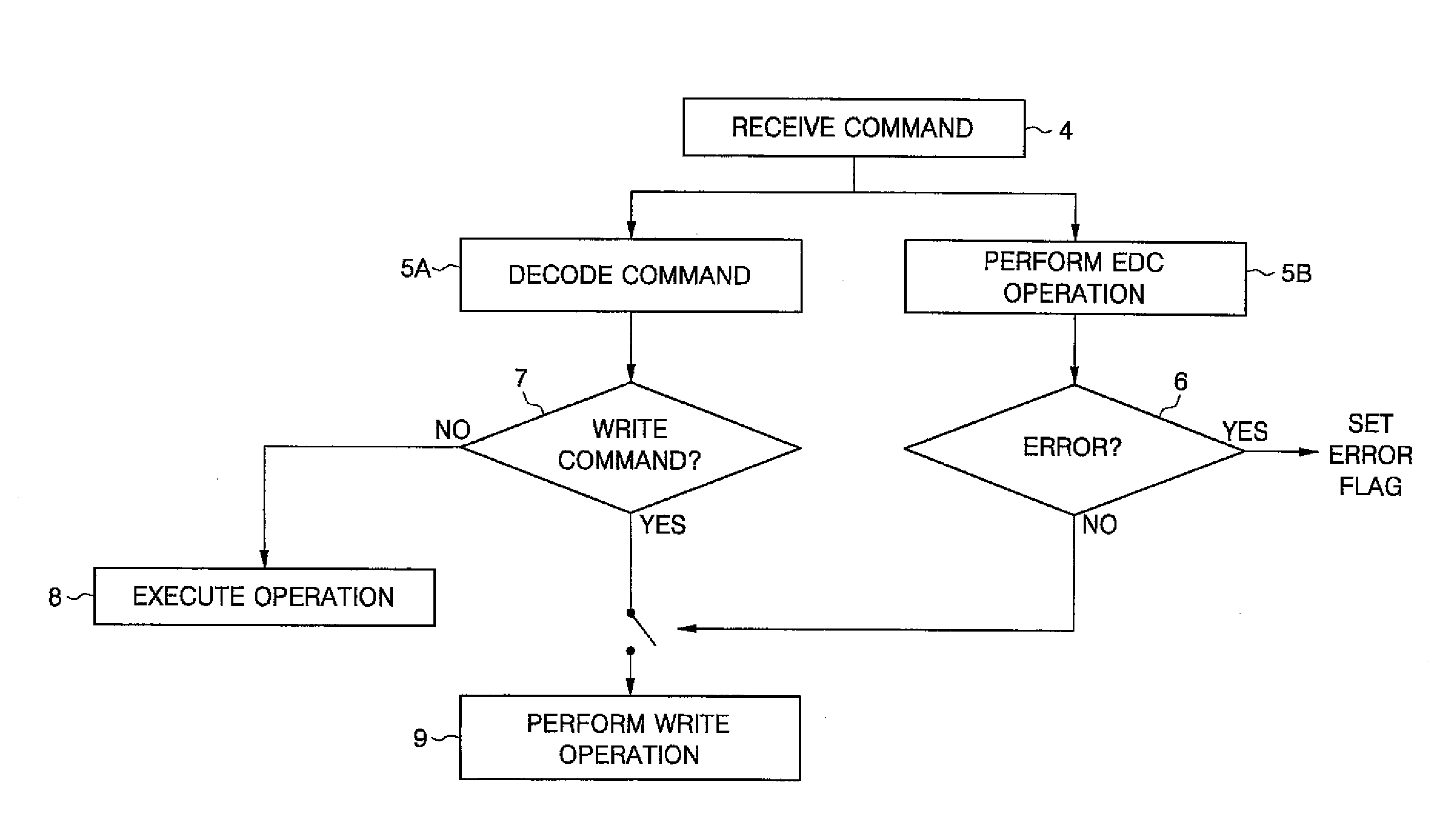
[0049]In one aspect, embodiments of the invention address the issue of increasing command execution latency within a memory system incorporating EDC capabilities. Conventional memory systems sequentially execute commands only after finishing a corresponding EDC operation. When EDC data is communicated from a memory controller to a memory in relation to a command, an EDC operation must be performed to verify the accuracy of the data associated with the command (e.g., control data, address data, etc.) before the command can be executed in the memory. This sequential execution of the EDC operation followed by the command oper...


PUM


Abstract

A memory system including a memory controller and a memory and a related method are disclosed. The method includes communicating a command and error detection/correction (EDC) data associated with the command from the memory controller to the memory, decoding the command and executing an EDC operation related to the EDC data in parallel, and if the command is a write command, delaying execution of a write operation indicated by the write command until completion of the EDC operation, else immediately executing an operation indicated by the command without regard to completion of the EDC operation.

Description

CROSS REFERENCE TO RELATED APPLICATION[0001]This application claims priority to Korean Patent Application No. 10-2007-0013179 filed Feb. 8, 2007, the subject matter of which is hereby incorporated by reference.BACKGROUND OF THE INVENTION[0002]1. Field of the Invention[0003]The invention relates generally to memory systems and methods of handling memory system commands.[0004]2. Description of Related Art[0005]The concept of a “memory system” now encompasses a great variety of circuits and related control methods enabling the transfer, storage and retrieval of digital data. Once memory systems were associated with only computers systems and similar computational logic platforms. Now, a great host of consumer products ranging from cell phones to automobiles to refrigerators include memory systems of varying complexity.[0006]A generic memory system is conceptually illustrated in Figure (FIG.) 1, wherein a memory 2 is provided to store data received from a memory controller 1 via a chann...

Claims


Application Information

Patent Timeline
Patent Type & Authority Applications(United States)
IPC IPC(8): G06F11/10
CPCG06F11/1008G11C29/00
Inventor LEE, JUNG-BAE
Owner SAMSUNG ELECTRONICS CO LTD
Why Eureka
Try Eureka