Temperature sensing apparatus and methods for treatment devices used to deliver high frequency energy to tissue

a technology of high frequency energy and thermal sensing, which is applied in the direction of prosthesis, instruments, therapy, etc., can solve the problems of slow thermal response of the thermistor, the temperature readings of the thermistor may not reflect the actual temperature of adjacent structures, and the contraction of the tissue and tissue tightening, so as to improve the thermal sensing effect and reduce the impa

Inactive Publication Date: 2008-08-21
THERMAGE INC
View PDF45 Cites 40 Cited by
  • Summary
  • Abstract
  • Description
  • Claims
  • Application Information

AI Technical Summary

Benefits of technology

[0015]The invention is generally directed to skin condition treatment apparatus and methods that deliver electromagnetic energy with improved thermal sensing. The improved thermal sensing may eliminate or, at the least, reduce the impact associated with the artifacts of traditional temperature sensing.

Problems solved by technology

The inflammatory response of the tissue causes new collagen to be generated over time (between three days and six months following treatment), which results in further tissue contraction and tissue tightening.
Consequently, the temperature readings from the thermistors may not be representative of, or reflect, the actual temperature of adjacent structures, such as the treatment tip or the patient's skin.
These influences may slow the thermal response of the thermistor and degrade the accuracy of the estimate of the skin temperature.
The limited isolation of the thermistors from the cryogen introduces errors into determinations of the skin temperature from the temperature readings of the treatment tip temperature.
Hence, overheating of the patient's skin may not be detected in a timely manner during the delivery of high frequency energy.
The undesirable result is that skin damage may occur before measures are taken to indicate the occurrence of overheating to the clinician or to otherwise remedy the overheating.
Moreover, inaccuracies in the detected changes in skin temperature may result in poor control over the timing of individual pulses of cryogen spray directed toward the electrode.
Large differences between the thermal mass of the thermistor and the thermal mass of the thin electrode may precipitate a large temperature difference between the thermistor, on one hand, and the electrode assembly and its electrode, on the other hand.
For example, a spray of cryogen may reduce the temperature of the electrode by 50° C. and the temperature of the thermistor by only 5° C. Because the controller operates under the assumption that the temperature measured by the thermistor is nominally representative of the electrode and skin temperatures, the electrode may be sprayed prematurely with cryogen because this fundamental assumption is incorrect.
However, the package for a surface-mounted thermistor would present an irregularity or bump in the otherwise substantially planar patient-contacting surface.
Although the thermistor may be isolated from the artifacts caused by direct contact with the cryogen, the surface irregularity would be evident to the patient.
This limits the effectiveness of the software algorithm in responding to a condition in which one or more edges of the electrode have a non-contacting relationship with the skin when the electrode is energized.
Heating or cooling of the skin temperature during treatment may also contribute to limiting the response effectiveness of the software lifted algorithm.
A deficiency of this workaround is that not all of the thermistors may be cooled to the same temperature.
When the cryogen spray is resumed, the lifted algorithm cannot be used to reliably confirm that contact is sustained at each corner of the treatment tip.
The temperature readings from the thermistors in conventional treatment tips are currently not used to regulate the amount of delivered energy during patient treatment because of an inability to accurately measure the skin surface temperature or to be used to estimate the subsurface dermal temperature.

Method used


Image

  • Temperature sensing apparatus and methods for treatment devices used to deliver high frequency energy to tissue
  • Temperature sensing apparatus and methods for treatment devices used to deliver high frequency energy to tissue
  • Temperature sensing apparatus and methods for treatment devices used to deliver high frequency energy to tissue

Examples


Embodiment Construction

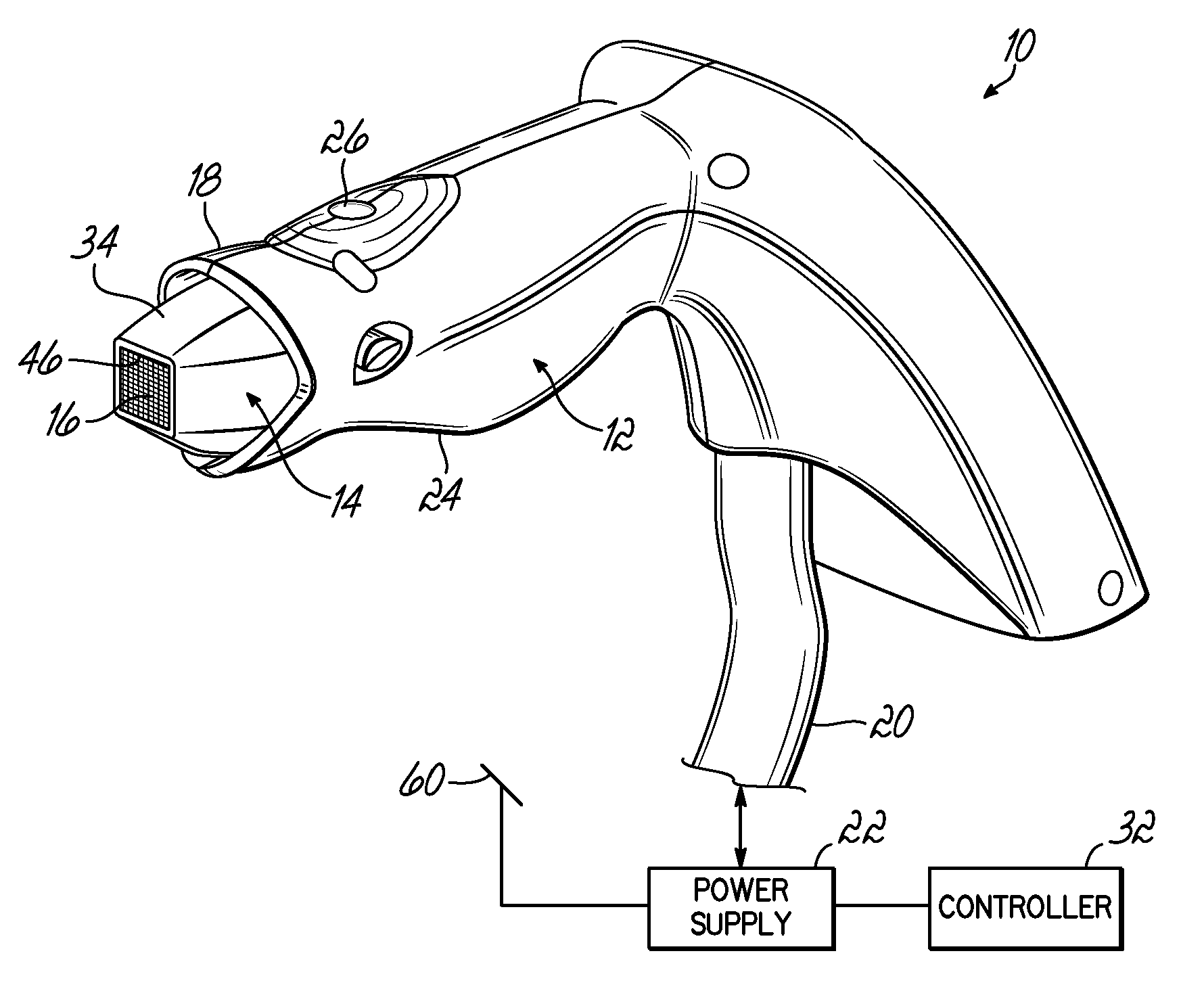
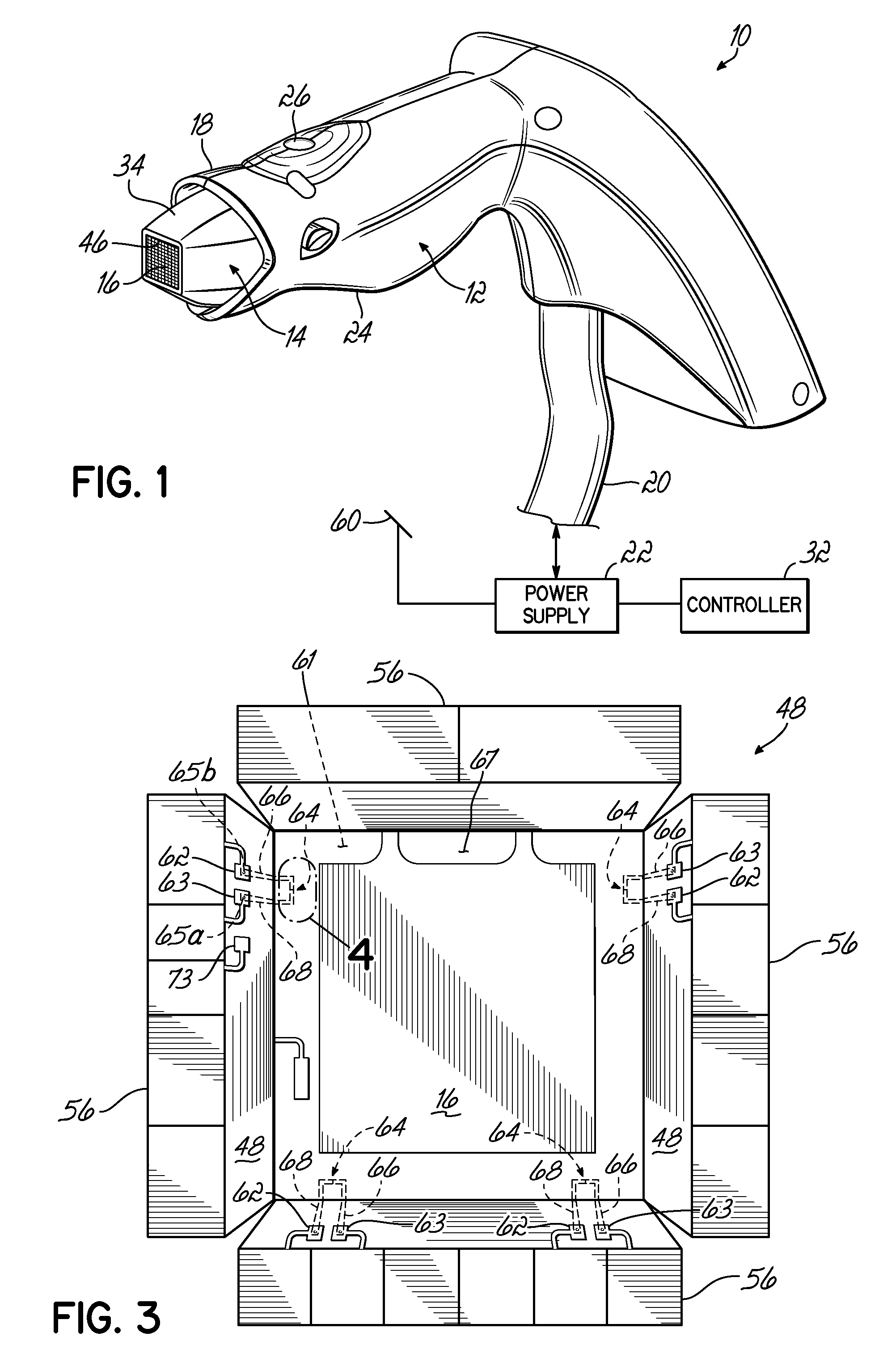
[0041]With reference to FIG. 1, a treatment apparatus or handpiece 10 includes a housing 12 typically composed of a plastic or polymer material, such as a cured polymer resin, that is molded, such as by an injection molding process, into a three-dimensional shape. Releasably coupled with the housing 12 is a delivery device in the representative form of an electrode structure or assembly 14 (i.e., treatment tip) having a leading end carrying an electrode 16, which protrudes from a shroud 18 defined at one end of the housing 12. When the electrode assembly 14 is coupled mechanically with the housing 12, the electrode 16 is exposed and visible.

[0042]Housing 12 provides a suitable interface for connection to an electrical connecting cable 20 that includes insulated and shielded conductors or wires (not shown) that electrically couple the electrode assembly 14 with a high frequency electromagnetic generator or power supply 22. Electrical connections (discussed below) inside a hollow inte...


PUM


Abstract

Apparatus and methods for delivering high frequency energy to tissue with improved temperature sensing. The treatment apparatus may be a delivery device positionable adjacent to the tissue. The delivery device may further include an electrode adapted to deliver high frequency energy to the tissue and at least one thermal sensor. In one embodiment, the thermal sensor may include a thermocouple junction of dissimilar metals formed by either thin film or thick film techniques. Alternatively, the thermal sensor may include a body composed of a resistive material having a resistance that varies with temperature to an extent sufficient to measure the skin temperature. A region of the delivery device near the thermal sensor may be heated, before skin contact is established during treatment, for purposes of detecting contact by the occurrence of heat loss from the delivery device region.

Description

FIELD OF THE INVENTION[0001]This application claims the benefit of U.S. Provisional Application No. 60 / 890,295, filed Feb. 16, 2007, which is hereby incorporated by reference herein in its entirety.FIELD OF THE INVENTION[0002]The invention generally relates to apparatus and methods for treating tissue with high frequency energy and, more particularly, relates to apparatus and methods for delivering high frequency energy and thermal sensing associated with such apparatus and methods.BACKGROUND OF THE INVENTION[0003]Devices that can treat tissue non-invasively are extensively used to treat numerous diverse skin conditions. Among other uses, non-invasive energy delivery devices may be used to tighten loose skin to make a patient appear younger, remove wrinkles and fine lines, contour the skin, remove skin spots or hair, or kill bacteria. Such non-invasive energy delivery devices emit electromagnetic energy in different regions of the electromagnetic spectrum for tissue treatment. Speci...

Claims


Application Information

Patent Timeline
Patent Type & Authority Applications(United States)
IPC IPC(8): A61B18/18
CPCA61B18/14A61B18/18A61B18/1815A61B2017/00088A61B2017/00092A61B2018/00702G01K13/002A61B2018/00797A61N1/06A61N1/328A61N1/403G01K7/04A61B2018/00791G01K13/20
Inventor WEBER, BRYAN
Owner THERMAGE INC
Why Eureka
Try Eureka