Light source device assembly

Inactive Publication Date: 2008-08-28
FRONTEND ANALOG & DIGITAL TECH CORP +1
View PDF9 Cites 1 Cited by
  • Summary
  • Abstract
  • Description
  • Claims
  • Application Information

AI Technical Summary

Benefits of technology

[0015]The objective of the invention is to provide a novel light source device assembly that may be processed and assembled easily, with relatively high yield rates.
[0016]Another objective of this invention is to provide a light source device assembly with a simplified structure.
[0017]Another objective of this invention is to provide a light source device that may be prepared under relatively low costs.
[0019]According to the present invention, a novel light source device assembly is provided. The light source device assembly of this invention comprises a substrate, a plurality of light source devices and a heat dissipation plate. In the substrate, a plurality of through holes is provided at a plurality of predetermined positions, to support the plurality of light source devices. In the heat dissipation plate, at a plurality of predetermined positions corresponding to the positions of the plurality of through holes, a plurality of upwardly protruded tongue pieces is provided, in a manner that each tongue piece is in contact with its respectively corresponding light source device in the plurality of through holes. Metal solders may be applied in between the plurality of tongue pieces and their corresponding plurality of light source devices to enhance the heat dissipation efficiencies. Necessary circuitry may be provided in the substrate and the circuitry may be in connection with the light source device electrically.
[0020]In the present invention, the heat dissipation plate contacts firmly with all the light source devices, whereby the heat dissipation efficiency of the assembly is enhanced. The tongue pieces of the heat dissipation plate are formed automatically by using a presser. No additional components are needed. The metal solders may be applied to the top surface of the tongue pieces using a machine. The costs and process of the light source device assembly are thus saved and the yield rate of the assembling process is thus increased.

Problems solved by technology

First, the heat dissipation plate 3 is a plan plate. When the light source device is an LED array, it would include a plurality of LED bulbs, in the number of from several tens to several hundreds. To support such an LED array, the substrate and the heat dissipation plate need to be in a large space. As a result, the contacts between the LED bulbs and the heat dissipation plate are not ensured. Although the use of the heat sink 35 solves this problem to some extends, such an additional component and its assembly process contribute to increasing the costs and difficulties in the processing and assembly of the light source device assembly.
The use of the thermal adhesive or the thermal grease 31 makes the light source device assembly bulky.
The costs in the manufacture of the light source device assembly are thus made higher, adding to the low yield rate of the products.
This technology, however, is high-cost and is not practicable since in the MCPCB the electricity, the electronic signals and the heat share the same channels.

Method used


Image

  • Light source device assembly
  • Light source device assembly
  • Light source device assembly

Examples


Embodiment Construction

[0024]The structure and the preparation of the embodiments of the invented light source device assembly will be described in details in the followings. It shall be noted that the detailed descriptions are used to illustrate the present invention. They shall not be used to limit the scope of the invention. The scope of protection of the present invention shall only be limited by the claims.

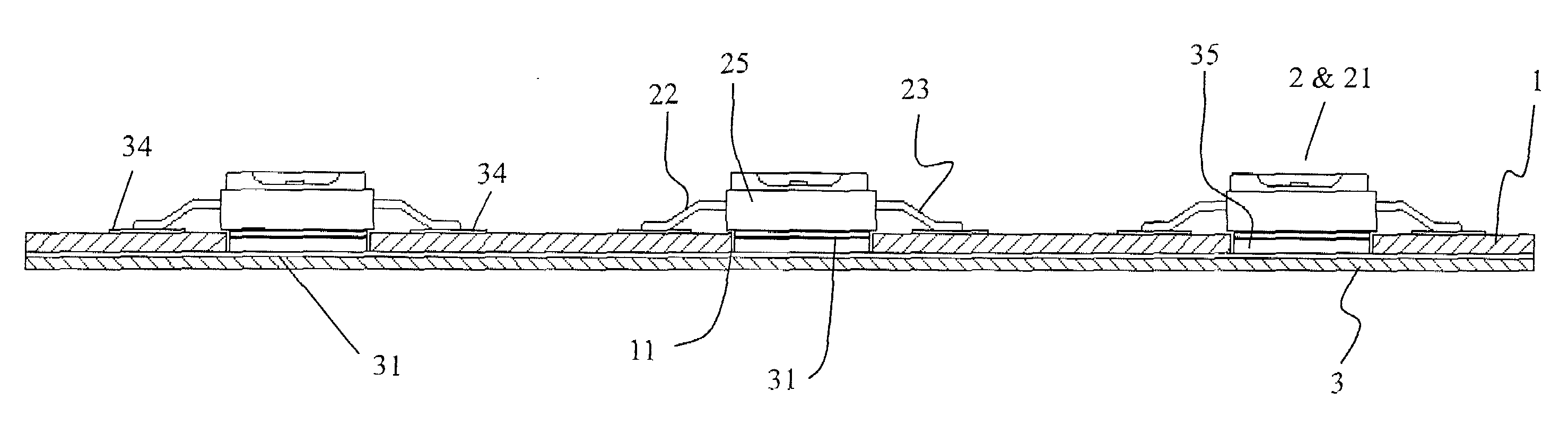
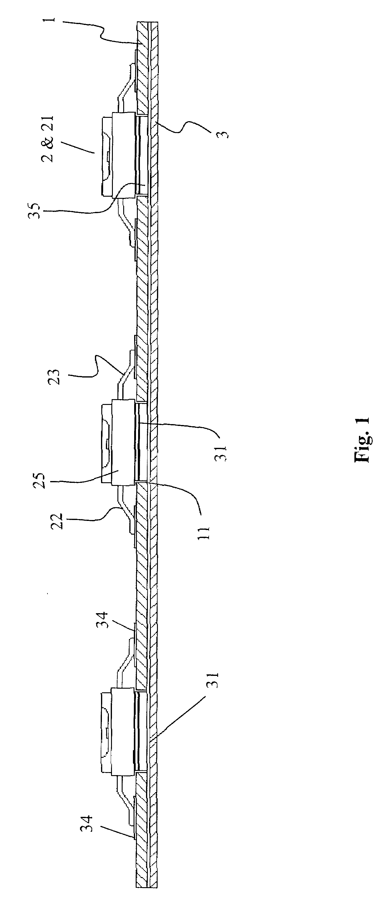
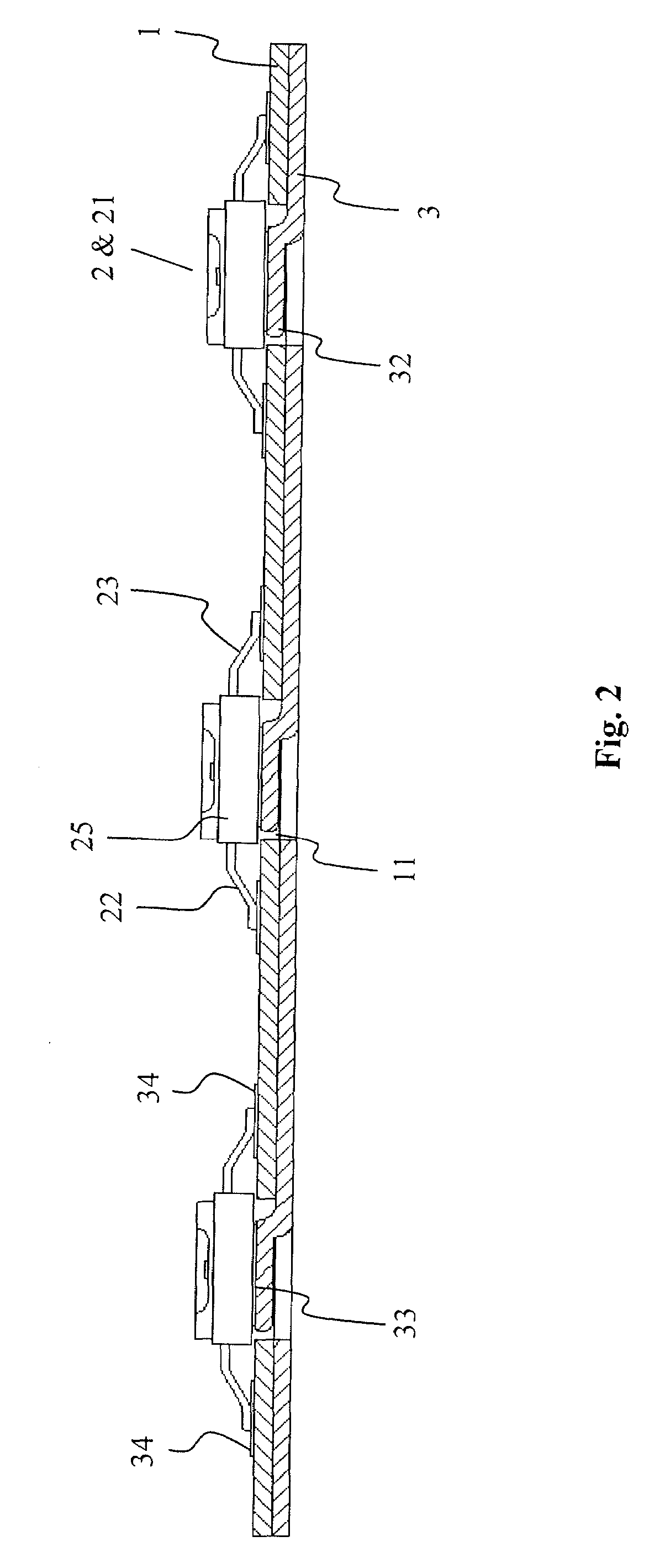
[0025]FIG. 2 illustrates the cross-sectional view of one embodiment of the light source device assembly of this invention. Components that are the same as those in FIG. 1 are labeled with the same numbers. As shown in FIG. 2, the light source device assembly of this invention also includes a substrate 1, a plurality of light source devices 2, 2 positioned in the plurality of through holes 11, 11 provided in the substrate 1 and a heat dissipation plate 3 positioned under the substrate 1 and in connection with the plurality of light source devices 2, 2.

[0026]In the present invention, the substrate 1 ...


PUM


Abstract

A novel light source device assembly comprises a substrate, a plurality of light source devices and a heat dissipation plate. In the substrate, a plurality of through holes is provided at a plurality of predetermined positions, to support the plurality of light source devices. In the heat dissipation plate, at positions corresponding to that of the plurality of through holes, a plurality of upwardly protruded tongue pieces is provided, whereby each tongue piece is in contact with its respectively corresponding light source device in the plurality of through holes. Metal solders may be applied in between the plurality of tongue pieces and their corresponding plurality of light source devices to enhance the heat dissipation efficiencies. Necessary circuitry may be provided in the substrate and the circuitry may be in connection with the light source device electrically.

Description

FIELD OF THE INVENTION[0001]The present invention relates to a light source device assembly, especially to a light source assembly using the light emitting diode (LED) array as its light source. The present invention also discloses a heat dissipation plate to be used in the invented light source device assembly.BACKGROUND OF THE INVENTION[0002]Due to the enhancement of the light generation efficiency of the light emitting diode (LED), the lighting device using the small-scaled and highly efficient light emitting component such as the LED has become popular in the past few years. Nowadays a plurality of LED lighting equipments is made commercially available, including the LED lights or indicator lights and other lighting devices or displaying devices that use the LED array as their light sources.[0003]When the LED is used as the light source an array or a matrix of LED's is needed. In such a case, the heat dissipation is one of the major concerns. Especially when the LED's are positi...

Claims


Application Information

Patent Timeline
IPC IPC(8): F21V21/00
CPCF21K9/00H05K1/0204H05K3/0061H05K2201/0382F21V29/89H05K2201/09054H05K2201/10106F21V29/20F21V29/83H05K2201/0397F21Y2115/10
Inventor CHEN, WEN-HOCHEN, MING-KANGYANG, MAO-CHING
Owner FRONTEND ANALOG & DIGITAL TECH CORP
Why Eureka
Try Eureka