Power Supply Device For Vehicle

a technology for power supply devices and vehicles, applied in electric devices, battery/fuel cell control arrangements, battery/cell propulsion, etc., can solve the problems of only being able to charge, disadvantageous removal, and increasing vehicle weigh

Inactive Publication Date: 2008-08-28
TOYOTA JIDOSHA KK
View PDF7 Cites 17 Cited by
  • Summary
  • Abstract
  • Description
  • Claims
  • Application Information

AI Technical Summary

Benefits of technology

[0019]According to the present invention, charging can be performed with the use of a low-cost power generation device provided outside the vehicle, and only a small amount of fuel for supply is required.

Problems solved by technology

In other words, immovable installation is disadvantageous in that charging can only be performed at the location where the charging device is immovably installed.
In contrast, if the charging device is mounted on a vehicle, there arises a problem of vehicle weight increase.
However, there may be a case where a vehicle storage space is apart from a house.
In such a case, an electrical work for installing an electric power line for the commercial electric power in the vehicle storage space involves great expense.

Method used


Image

  • Power Supply Device For Vehicle
  • Power Supply Device For Vehicle
  • Power Supply Device For Vehicle

Examples


first embodiment

[0030]Some of the stand-alone power generation devices that are not connected to a commercial electric power system, such as a wind power generation device and a solar power generation device, may exhibit fluctuations in electric power supplied thereby. If such a power generation device, which cannot provide stable electric power supply, is used as a charging device for an electric vehicle, time required for completion of charging may fluctuate, and hence such a device may sometimes be problematic for serving as dedicated energy supply means.

[0031]In contrast, in recent years, attention has been focused on a hybrid vehicle that uses a motor and an engine in combination for driving a wheel, as an environmental-friendly vehicle. As to the hybrid vehicle, fuel can separately be supplied as energy supply means, and hence the battery is not necessarily charged to a charge completion state. Accordingly, fuel consumption can be reduced by a combined use of fuel and energy supply from the s...

second embodiment

[0119]In the first embodiment, there has been explained the case where a two-phase alternating current or a direct current is provided from the power generation device connected to the vehicle. In a second embodiment, there will be described the case where a three-phase alternating current is provided from a power generation device.

[0120]FIG. 8 is a circuit diagram showing a configuration of a vehicle 200 according to the second embodiment.

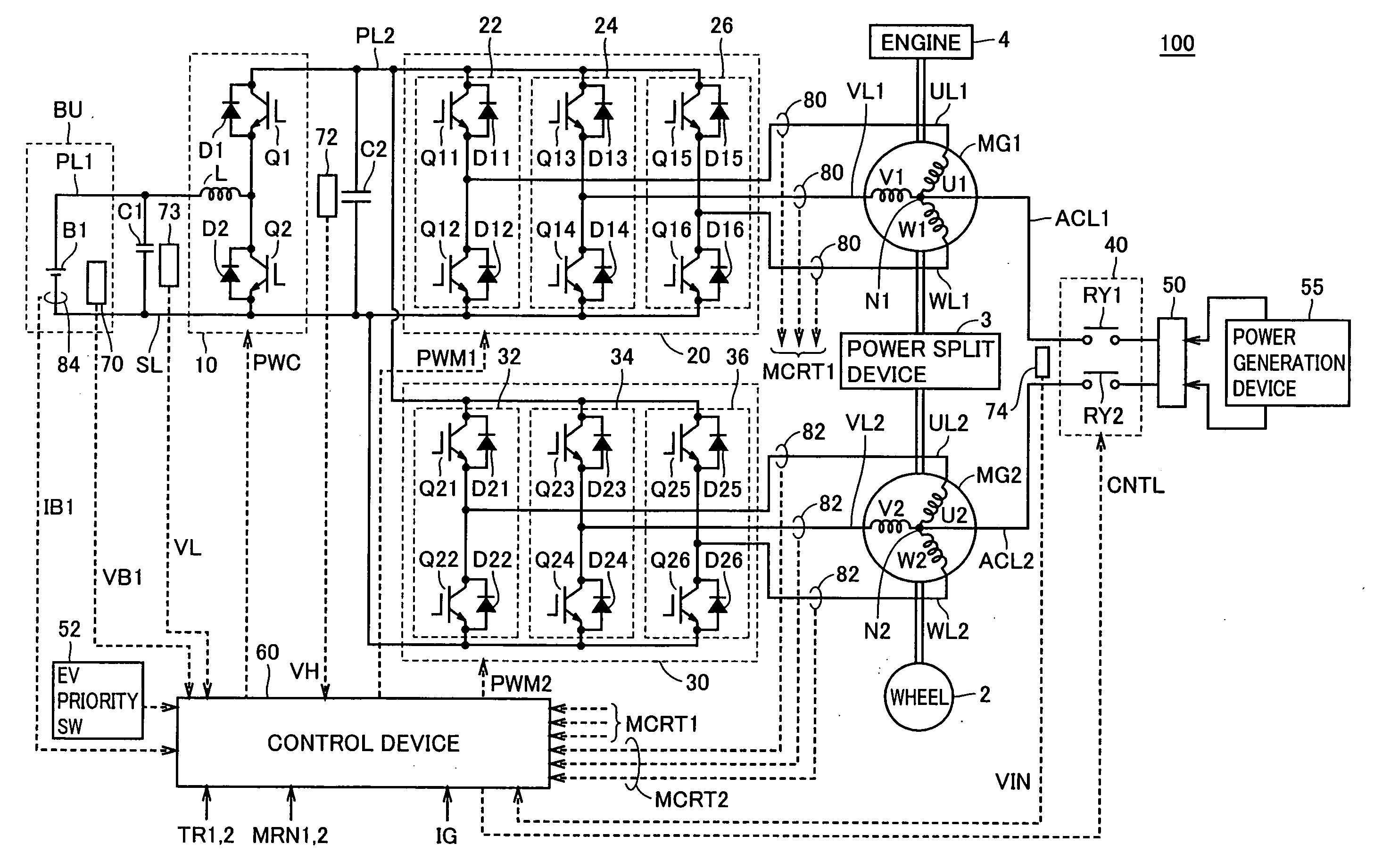
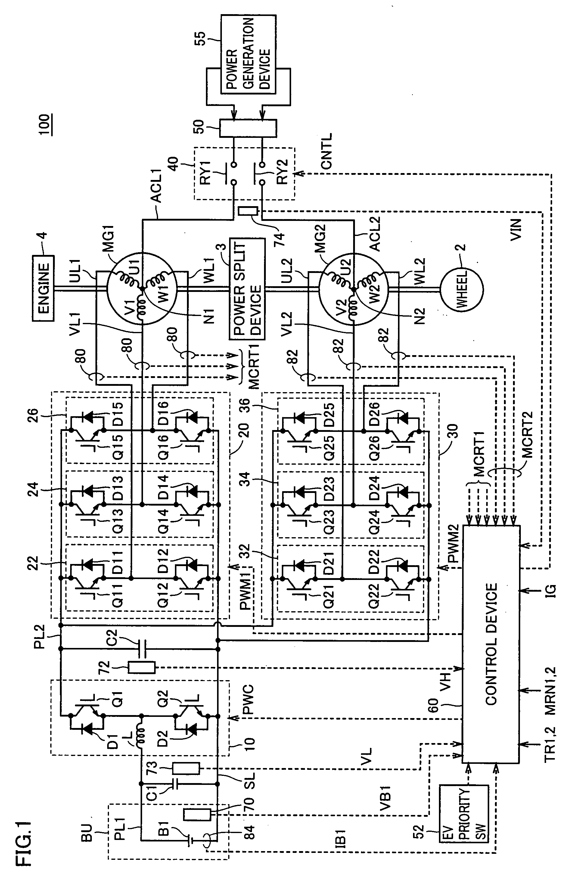
[0121]With reference to FIG. 8, vehicle 200 includes a connection switching unit 240 and a connector 250 instead of voltage sensor 74, relay circuit 40, and connector 50 in the configuration of vehicle 100 shown in FIG. 1. Configurations of other portions are the same as those in vehicle 100 shown in FIG. 1, and hence the description thereof will not be repeated.

[0122]A power generation device 255 provided at home or the like is connected to connector 250 when the vehicle is stopped. Power generation device 255 is a wind power generation device, f...


PUM


Abstract

A power supply device for a vehicle is provided with: a battery serving as an electric storage device; a connection unit for receiving electric power provided from a power generation device for wind power generation, for example, and charging the electric storage device, the power generation device being provided outside the vehicle and exhibiting fluctuations in electric power generated thereby; and an electric power conversion unit which, during driving, operates as a load circuit and which, during charging for receiving electric power from the power generation device, senses fluctuations in voltage, and converts the electric power to obtain a current and a voltage suitable for charging the electric storage device. The electric power conversion unit includes a control device controlling first and second inverters such that electric power provided to first and second terminals is converted into direct-current electric power and provided to the electric storage device.

Description

TECHNICAL FIELD[0001]The present invention relates to a power supply device for a vehicle, and particularly relates to a power supply device for a vehicle, capable of being charged externally.BACKGROUND ART[0002]An electric vehicle requires a charging device for charging a battery with a direct current. The charging device may be mounted on a vehicle, or may be installed immovably at a certain location.[0003]If the charging device is installed immovably at a certain location, it is necessary to move an electric vehicle to the location for charging. In other words, immovable installation is disadvantageous in that charging can only be performed at the location where the charging device is immovably installed.[0004]In contrast, if the charging device is mounted on a vehicle, there arises a problem of vehicle weight increase.[0005]Japanese Patent Laying-Open No. 04-295202 discloses a motor-driving device and a motive power-processing device used in an electrically-powered vehicle. In t...

Claims


Application Information

Patent Timeline
Patent Type & Authority Applications(United States)
IPC IPC(8): H02M7/797B60L50/15B60L50/16
CPCB60L8/00Y02T10/7083B60L2260/56B60L9/18B60L15/007B60L15/20B60L2210/14B60L2210/30B60L2210/40B60L2220/54B60L2220/56B60L2240/421B60L2240/423B60L2240/441B60L2240/443B60L2240/547B60L2240/549B60L2240/527Y02T90/14Y04S10/126Y04S30/14B60L53/14B60L50/61B60L50/16B60L53/24B60L55/00B60L53/63B60L53/65B60L58/12B60L53/51B60L53/52Y02E60/00Y02T10/62Y02T10/64Y02T10/70Y02T10/7072Y02T10/72Y02T90/12Y02T90/167Y02T90/16
Inventor NAKAMURA, MAKOTOOYOBE, HICHIROSAIISHIKAWA, TETSUHIRO
Owner TOYOTA JIDOSHA KK
Why Eureka
Try Eureka