Power Converter Apparatus

a power converter and diode technology, applied in the direction of power conversion systems, electrical apparatus, ac-dc conversion without reversal, etc., can solve the problems of increasing comparatively large power loss inside etc., to reduce power loss in the diode bridge element and save energy in various electric equipmen

Inactive Publication Date: 2008-08-28
SANDEN CORP
View PDF2 Cites 4 Cited by
  • Summary
  • Abstract
  • Description
  • Claims
  • Application Information

AI Technical Summary

Benefits of technology

[0015]The present invention is made in view of the above-described problems, and aims at providing a power converter apparatus which reduces power loss in a diode bridge element in order to achieve energy saving in various electric equipments.
[0020]According to the power converter apparatus of the present invention, with letting two diodes, which are parallel-connected, be one set, a diode bridge circuit is formed using four sets of these. Hence, it is possible to decrease a forward current, which flows into one diode, to almost a half in comparison with a case of using only one diode bridge element. Therefore, since a forward voltage of one diode also decreases thereby, it is possible to reduce power loss in two diode bridge elements in comparison with a conventional apparatus which used only one diode bridge element. For this reason, it is possible to reduce useless power consumption more than a conventional example to achieve energy saving of electric equipment by applying the present invention to power supply units in various electric equipments.

Problems solved by technology

Nevertheless, as shown in FIG. 3, when the diode bridge element 10 is used simply, a full load current flows through one diode bridge element 10, and hence, comparatively large power loss arises inside the diode bridge element 10.
For this reason, when the forward current increases, the forward voltage increases in connection with this, and in consequence, the power loss in the diode increases.

Method used


Image

  • Power Converter Apparatus
  • Power Converter Apparatus
  • Power Converter Apparatus

Examples


first embodiment

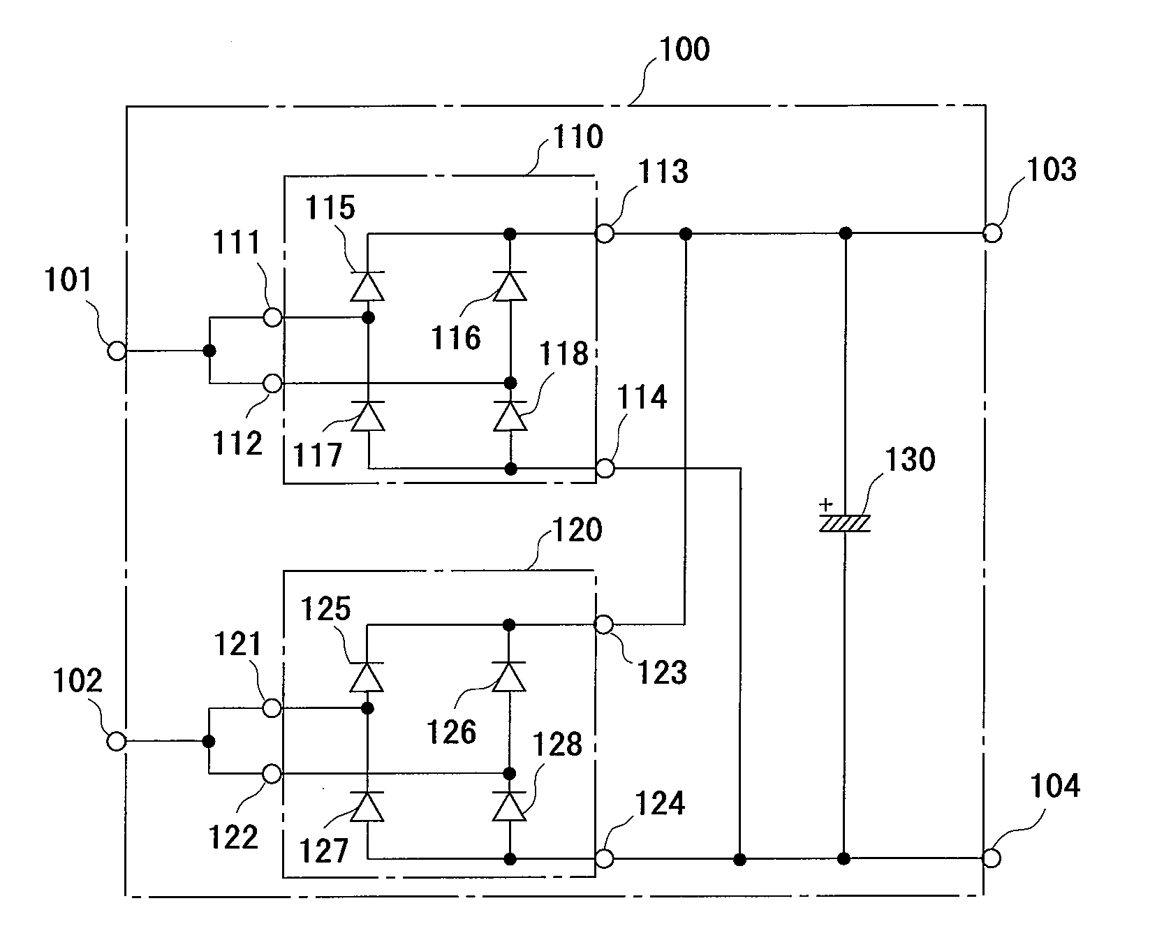
[0025]FIG. 1 is a circuit diagram showing a power converter apparatus of the present invention. In the diagram, a power converter apparatus 100 comprises two diode bridge elements 110 and 120, and a smoothing electrolytic capacitor (hereafter, this is simply called a capacitor) 130.

[0026]The one diode bridge element 110 has two input terminals 111 and 112 and two output terminals 113 and 114 outside as everyone knows, and has four diodes 115 to 118 inside. The one input terminal 111 is connected to an anode of the diode 115, and a cathode of the diode 117, and the another input terminal 112 is connected to an anode of the diode 116, and a cathode of the diode 118. Furthermore, the positive pole output terminal 113 is connected to cathodes of the diodes 115 and 116, and the negative pole output terminal 114 is connected to anodes of the diodes 117 and 118.

[0027]Similarly, the another diode bridge element 120 has two input terminals 121 and 122 and two output terminals 123 and 124 out...

second embodiment

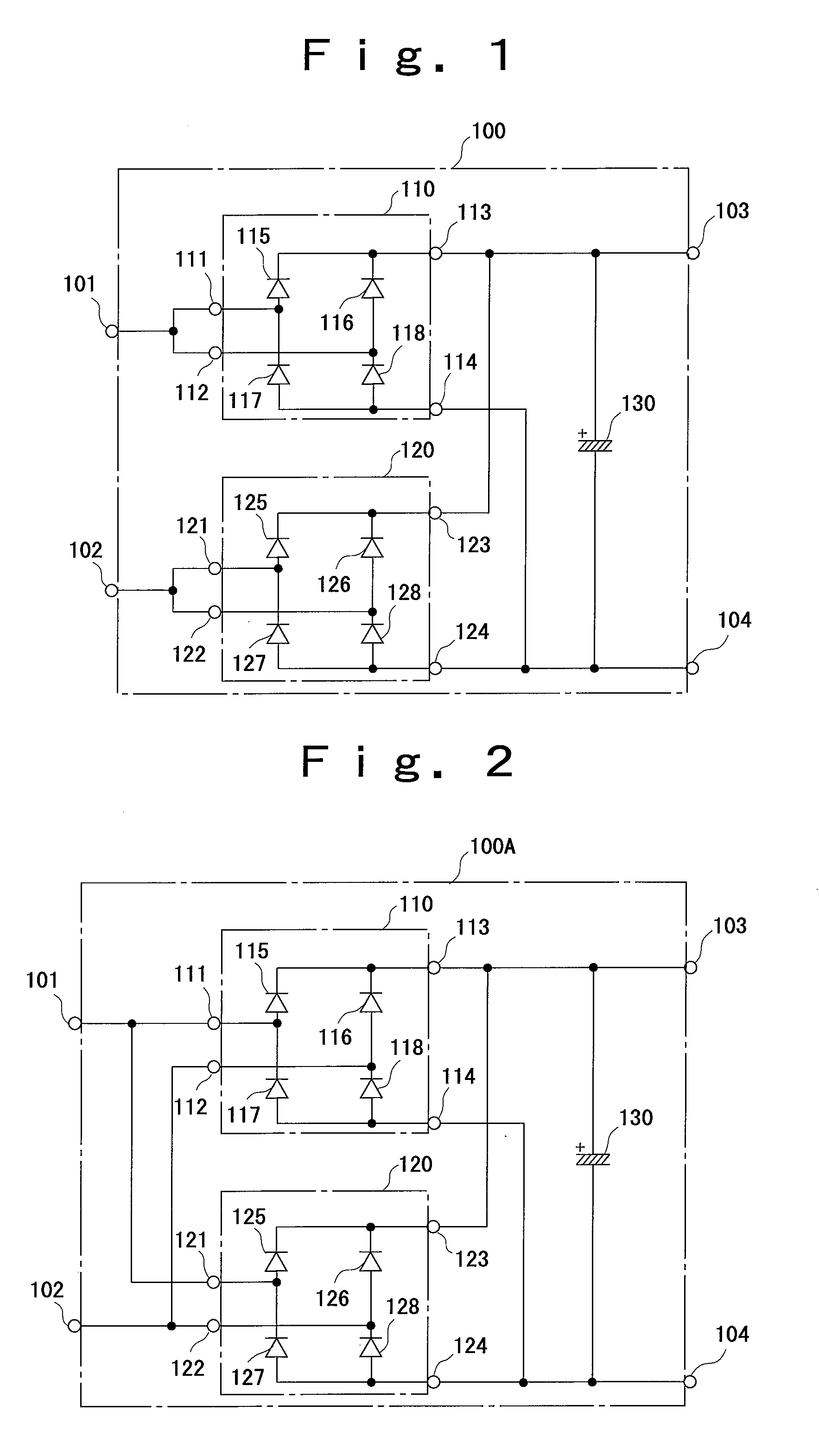
[0033]Although it is possible to obtain almost the same effect even if the diode bridge elements 110 and 120 are parallel-connected simply like the second embodiment shown in FIG. 2, in this case, characteristics of the diodes inside the diode bridge elements 110 and 120 are different in the respective elements 110 and 120. For this reason, when the diodes of the different diode bridge elements 110 and 120 are parallel-connected, there is a possibility that a current may not be shunted into respective diodes which are parallel-connected equally, and hence, a trouble may be generated in the reduction of power loss.

[0034]On the other hand, since the diodes in the same diode bridge elements 110 and 120 are parallel-connected in the power converter apparatus 100 in the first embodiment shown in FIG. 1, the characteristics of the diodes which are parallel-connected are the same. Hence, it is possible to make a current equally shunted into these diodes which are parallel-connected, and to...


PUM


Abstract

The present invention provides a power converter apparatus which reduces power loss in a diode bridge element in order to achieve energy saving. The power converter apparatus is equipped with two diode bridge elements, and reduces power loss in respective diodes by connecting two input terminals of the one diode bridge element to one AC input terminal of the power converter apparatus, connecting two input terminals of the another diode bridge element to another AC input terminal, connecting a positive pole output terminal to respective positive pole output terminals of the two diode bridge elements and a positive electrode terminal of a capacitor, and connecting a negative pole output terminal to respective negative pole output terminals of the two diode bridge elements, and a negative electrode terminal of the capacitor.

Description

BACKGROUND OF THE INVENTION [0001]1. Field of the Invention[0002]The present invention relates to a power converter apparatus which can be applied to power supply units of various electric equipments, and which converts an inputted AC power into DC power and outputs it.[0003]2. Description of the Related Art[0004]Heretofore, as this kind of apparatus, for example, a power converter apparatus disclosed in Japanese Patent Publication 7-31153 (Patent Document 1) and a power supply circuit disclosed in Japanese Patent Publication 2003-348846 (Patent Document 2) are known.[0005]The power converter apparatus disclosed in Patent Document 1 connects two half wave switching circuits after performing full wave rectification using a full wave rectifier circuit which is constructed of a diode bridge element, and opens and closes these half wave switching circuits to generate a high-frequency voltage.[0006]The power supply circuit disclosed in Patent Document 2 applies AC power to a primary wind...

Claims


Application Information

Patent Timeline
Patent Type & Authority Applications(United States)
IPC IPC(8): H02M7/06
CPCH02M7/08H02M7/06
Inventor TAKADA, KOUHEIMACHIDA, MIKOTO
Owner SANDEN CORP
Why Eureka
Try Eureka