System and Method for Time Aligning Signals in Transmitters

a time alignment and transmitter technology, applied in the field of communication systems, can solve problems such as difficulty in maintaining a delay between the signal path, time alignment resolution may be inadequate, and difficulty in achieving time alignment resolution, and achieve the effect of high speed operations

Inactive Publication Date: 2008-08-28
TEXAS INSTR INC
View PDF6 Cites 65 Cited by
  • Summary
  • Abstract
  • Description
  • Claims
  • Application Information

AI Technical Summary

Benefits of technology

[0009]In accordance with another embodiment, a method for adjusting a time alignment between separate signal paths is provided. The method includes characterizing the separate signal paths over a variety of conditions to produce delay settings for the separate signal paths, saving the delay settings, determining operating conditions, retrieving delay settings based on the operating conditions, and applying the delay settings

Problems solved by technology

For example, in a digital polar modulation transmitter, this may be a difficult task since both amplitude and phase (or frequency) paths comprise digital components that may operate on different clock domains in a d

Method used


Image

  • System and Method for Time Aligning Signals in Transmitters
  • System and Method for Time Aligning Signals in Transmitters
  • System and Method for Time Aligning Signals in Transmitters

Examples


Embodiment Construction

[0029]The making and using of the embodiments are discussed in detail below. It should be appreciated, however, that the present invention provides many applicable inventive concepts that can be embodied in a wide variety of specific contexts. The specific embodiments discussed are merely illustrative of specific ways to make and use the invention, and do not limit the scope of the invention.

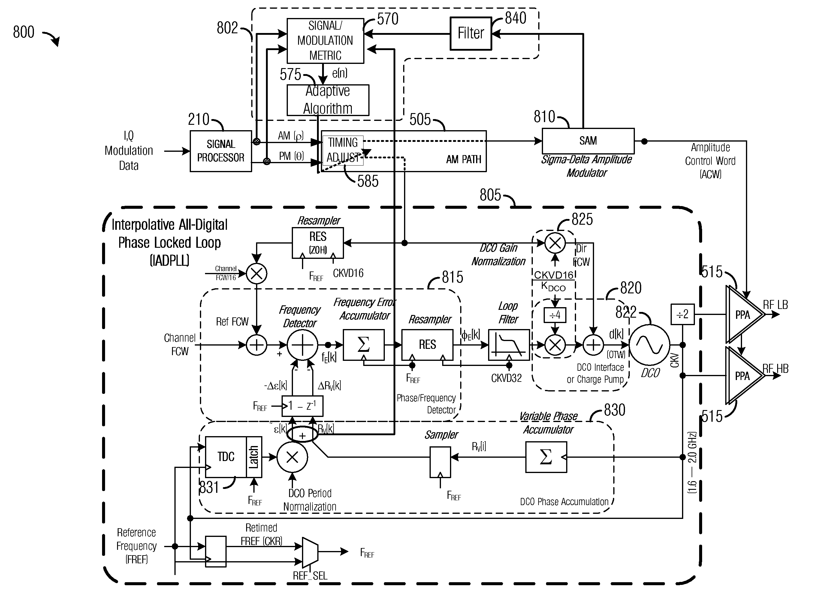
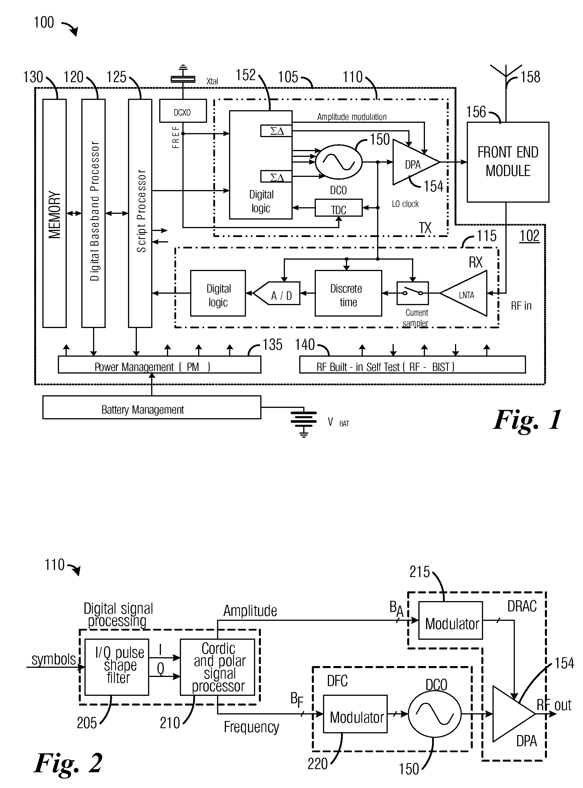
[0030]The embodiments will be described in a specific context, namely a wireless communications device adherent to a 2G or 3G cellular communications standard, such as Enhanced Data for GSM Evolution (EDGE), Wideband Code Division Multiple Access (WCDMA), Bluetooth—Enhanced Data Rate (BT-EDR), Wireless Local Area Network (WLAN), Worldwide Interoperability for Microwave Access (WiMAX), Long-Term Evolution (LTE), and so forth. The invention may also be applied, however, to other wireless communications devices adherent to other communications standards, wherein there is a desire to time align sign...


PUM


Abstract

A system and method for time aligning signals in transmitters. A transmitter includes a first signal path coupled to a first data input, a second signal path coupled to a second data input, an error signal energy source coupled to the first and second signal paths, the error signal energy source generates an error signal responsive to a time alignment difference between a first data stream and a second data stream, a time alignment circuit coupled to the error signal energy source, to the first and second data inputs, the time alignment circuit generates a digital control word responsive to the error signal, to the first and second data streams, and a timing adjust unit coupled to the time alignment circuit, to the first and second signal paths, the timing adjust unit inserts a delay proportional to the digital control word in either signal paths.

Description

[0001]This application claims the benefit of U.S. Provisional Application No. 60 / 891,916, filed on Feb. 27, 2007, entitled “A Method and Apparatus for Adaptive Equalization of the I / Q or RHO / THETA Imbalance in a Transmitter,” which application is hereby incorporated herein by reference.TECHNICAL FIELD[0002]The present invention relates generally to a system and method for communication systems, more particularly to a system and method for time aligning signals in transmitters.BACKGROUND[0003]Modem communications standards, such as Enhanced Data for GSM Evolution (EDGE), Wideband Code Division Multiple Access (WCDMA), Bluetooth—Enhanced Data Rate (BT-EDR), Wireless Local Area Network (WLAN), Worldwide Interoperability for Microwave Access (WiMAX), Long-Term Evolution (LTE), and so forth, impose strict performance requirements on transceivers. For example, for a transmitter utilizing a polar transmitter, stringent performance requirements exist for modulated close-in and far-out spect...

Claims


Application Information

Patent Timeline
IPC IPC(8): H04L7/00
CPCH04L27/367H04L27/361
Inventor MUHAMMAD, KHURRAMWAHEED, KHURRAM
Owner TEXAS INSTR INC
Why Eureka
Try Eureka