
Stent Graft With Strips to Promote Localized Healing

a technology of stent graft and proximal neck, which is applied in the field of stent grafts, can solve the problems of inability to perform conventional vascular graft surgery, inability to heal well to the vessel wall of the prior art endoluminal stent graft, and inability to achieve stable implant, improve localization healing, and reduce the healing time after the implant of an endoluminal stent graft

Inactive Publication Date: 2008-08-28
MEDTRONIC VASCULAR INC
View PDF7 Cites 11 Cited by
  • Summary
  • Abstract
  • Description
  • Claims
  • Application Information

AI Technical Summary

Benefits of technology

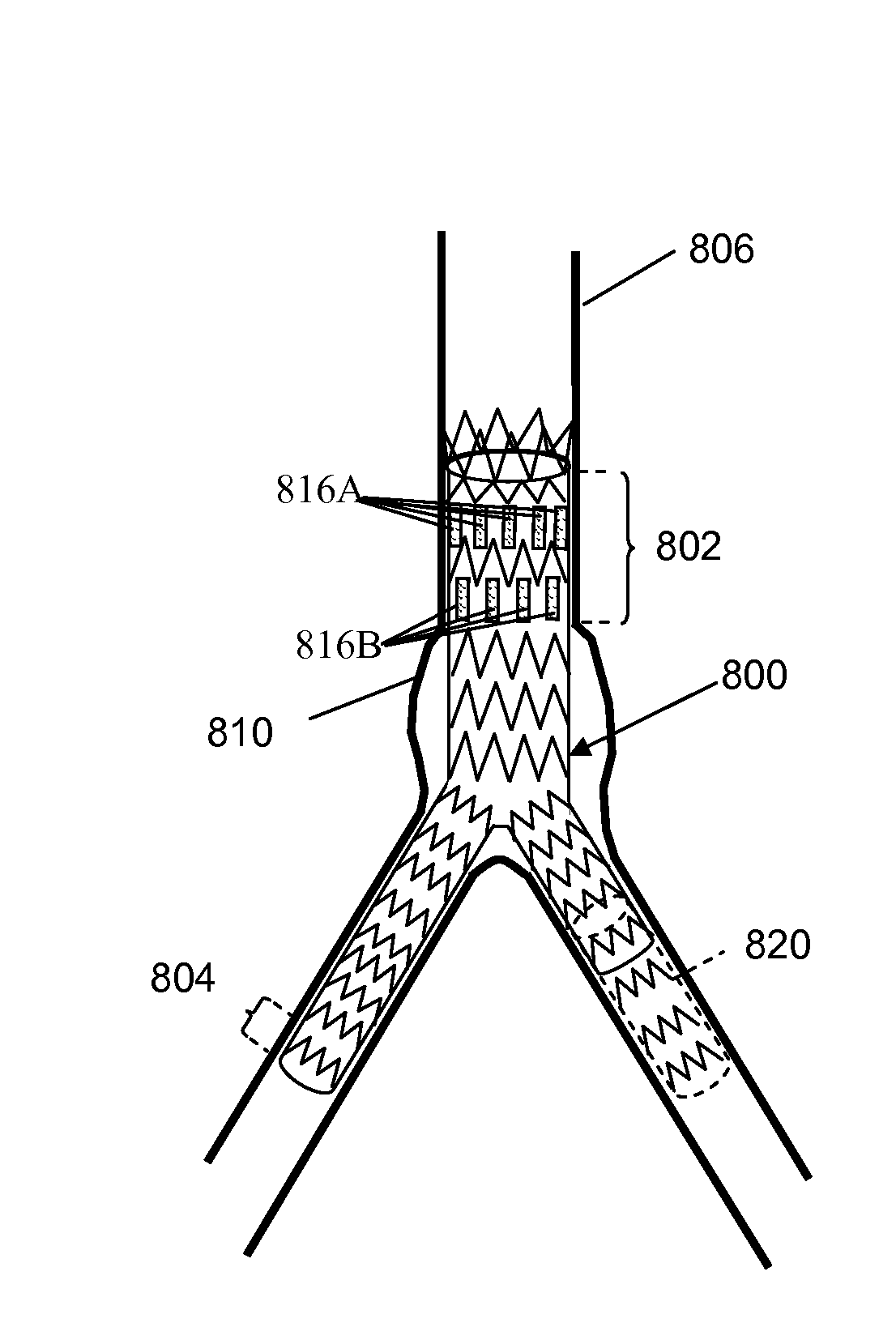
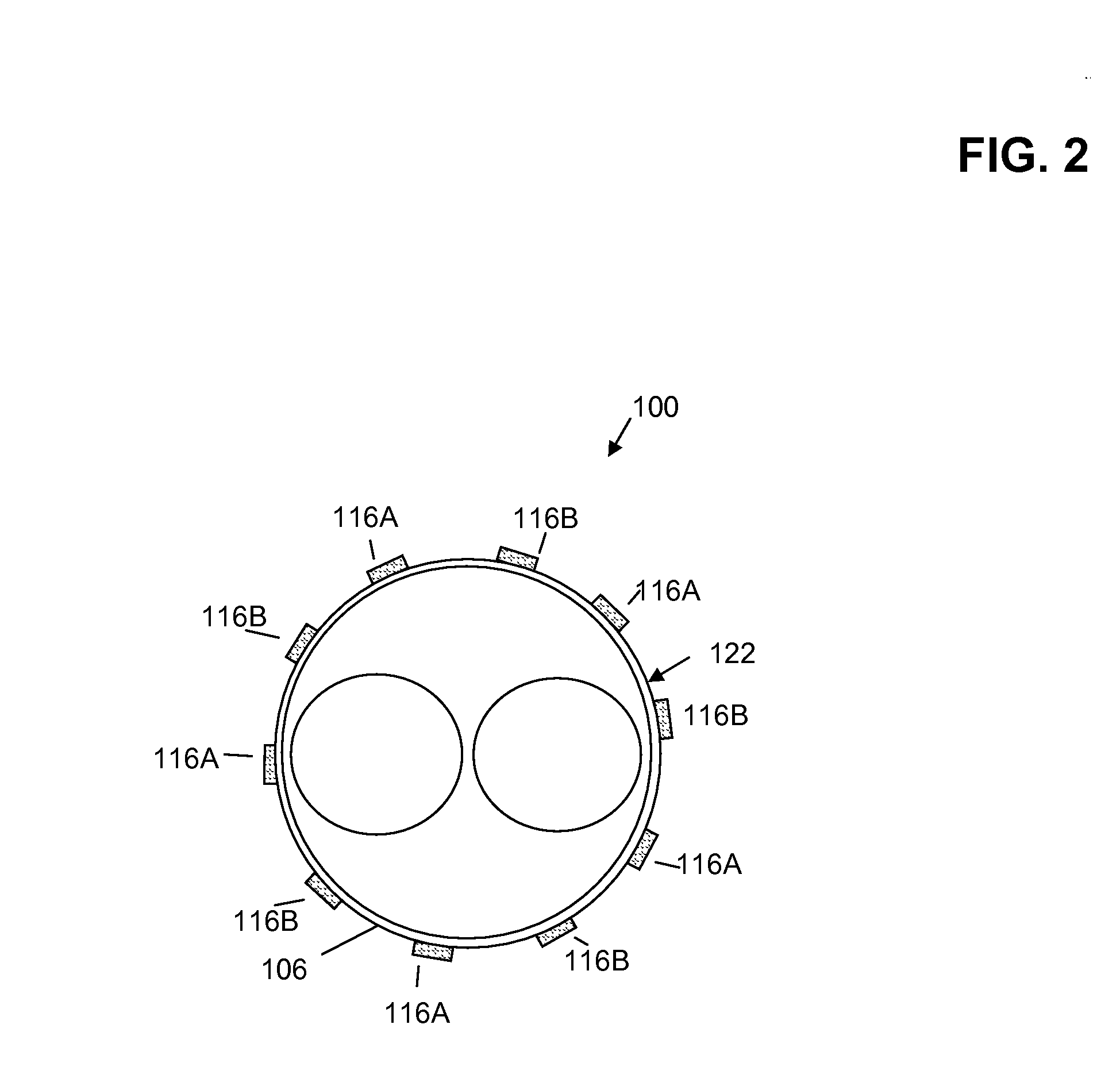
[0011]An endoluminal stent graft includes one or more segments of a healing promoter attached within a proximal anchor region of an endoluminal stent graft, and, optionally, within one or more distal anchor regions. When the endoluminal stent graft is positioned within a vessel, the segments of the healing promoter promote and guide the migration, proliferation and adhesion of vessel cells to the endoluminal stent graft to increase localized healing. Thus, healing time after implant of an endoluminal stent graft may be decreased and a more stable implant produced that is less susceptible to migration and / or endoleaks that could otherwise form at the sides of the proximal neck and the consequent feeding of the aneurysm sac.

Problems solved by technology

While considered an effective surgical technique, conventional vascular graft surgery however, is frequently not advisable for elderly patients or those patients weakened from cardiovascular and other diseases.
Unfortunately, prior art endoluminal stent grafts when implanted in some patients developed a number of technical problems with subsequent morbidity and / or mortality of the patient.
In particular, the proximal neck of the prior art endoluminal stent grafts did not heal in well to the vessel wall.
The lack of healing in and incorporation of the endoluminal stent graft at the aneurysm neck allowed the endoluminal stent graft to dislodge and migrate distally inside the aortic vessel permitting renewed feeding of blood and pressure to the aneurysm sac with the consequent risk of aneurysm rupture.

Method used


Image

  • Stent Graft With Strips to Promote Localized Healing
  • Stent Graft With Strips to Promote Localized Healing
  • Stent Graft With Strips to Promote Localized Healing

Examples


Embodiment Construction

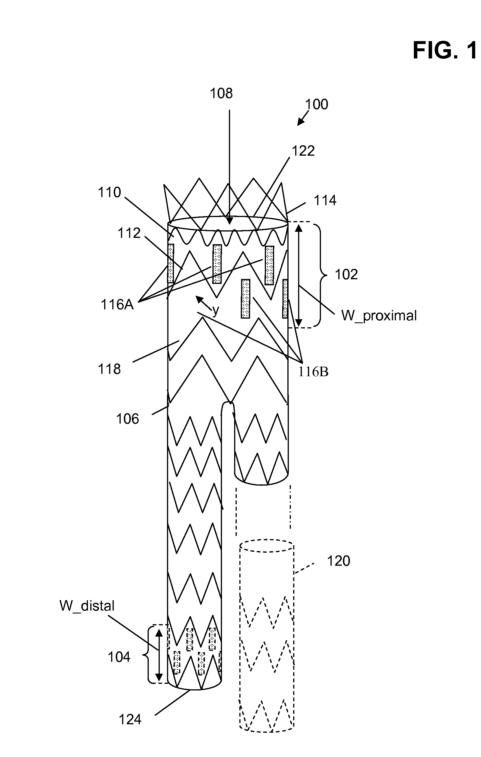
[0021]FIG. 1 illustrates one example of an endoluminal stent graft 100 including one or more segments 116A, 116B of a healing promoter. In FIG. 1, endoluminal stent graft 100, herein termed simply stent graft 100, includes: a graft material 106, i.e., a first material; one or more segments 116A, 116B of a healing promoter, i.e., one or more segments of a second material, attached to graft material 106; and a stent structure of springs attached to graft material 106, including a first (base) spring 110, a second (support) spring 112, an anchor spring 114, and other springs, such as support spring 118. As illustrated in FIG. 1, stent graft 100 is shaped to form a lumen 108 that bifurcates distally to accommodate branching of the aorta into smaller downstream vessels, e.g., the common iliac arteries. In some stent graft configurations, an extension 120 is included as part of main stent graft body 100.

[0022]In one example, graft material 106 is a material formed to limit the leakage of ...


PUM


Abstract

An endoluminal stent graft includes segments of a healing promoter to promote the “healing in” of the distal and / or proximal neck(s) of the endoluminal stent graft in a vessel, thus reducing the risk of migration and the occurrence of endoleaks that can formed at the side of the neck(s) and the consequent feeding of the aneurysm sac. In some applications, the segments of the healing promoter are located within a proximal anchor region located near the proximal neck opening of the endoluminal stent graft and, optionally, within one or more distal anchor regions located near one or more distal neck openings of the endoluminal stent graft. In other applications, the segments of the healing promoter are located within the proximal anchor region, but not the distal anchor region.

Description

RELATED APPLICATIONS[0001]This application claims the benefit of U.S. Provisional Patent Application 60 / 713,776 filed Sep. 2, 2005.BACKGROUND OF THE INVENTION[0002]1. Field of the Invention[0003]The present invention relates generally to stent grafts, and more particularly to improving healing associated with placement of an endoluminal stent graft in a vessel.[0004]2. Description of the Related Art[0005]Vascular aneurysms are the result of abnormal dilation of a blood vessel, usually resulting from disease and / or genetic predisposition, which can weaken the arterial wall and allow it to expand. While aneurysms can occur in any blood vessel, most occur in the aorta and peripheral arteries, with the majority of aortic aneurysms occurring in the abdominal aorta, usually beginning below the renal arteries and often extending distally into one or both of the iliac arteries.[0006]Aortic aneurysms are often treated in open surgical procedures where the diseased vessel segment is bypassed ...

Claims


Application Information

Patent Timeline
Patent Type & Authority Applications(United States)
IPC IPC(8): A61F2/06
CPCA61F2/07A61F2002/067A61F2/89A61F2250/0067A61F2002/075
Inventor KWITKIN, BRIANBILLY, DIDIERHENDRIKS, MARC
Owner MEDTRONIC VASCULAR INC
Learn More