Rotor for a generator

Active Publication Date: 2008-09-04
GENERAL ELECTRIC TECH GMBH
View PDF14 Cites 15 Cited by
  • Summary
  • Abstract
  • Description
  • Claims
  • Application Information

AI Technical Summary

Benefits of technology

[0020]Another aspect includes that the rotor has a rotor body with a first outside diameter, and two shaft ends with a second and third outside diameter, the first outside diameter is larger than the second and third outside diameters, and weld seams are provided in the region of the body and in the region of the shaft ends. As a result of this, large jumps in the outside diameter in the forgings for the shaft ends can be avoided.
[00

Problems solved by technology

In this case, it is disadvantageous that the narrow weld seams which are restricted to the edge, especially if they are still broken by the winding slots, enable only a limited strength of the welded rotor.
Additional weld seams in the slots certainly increase the strength to a certain extent, but are to be realized

Method used


Image

  • Rotor for a generator
  • Rotor for a generator
  • Rotor for a generator

Examples


Embodiment Construction

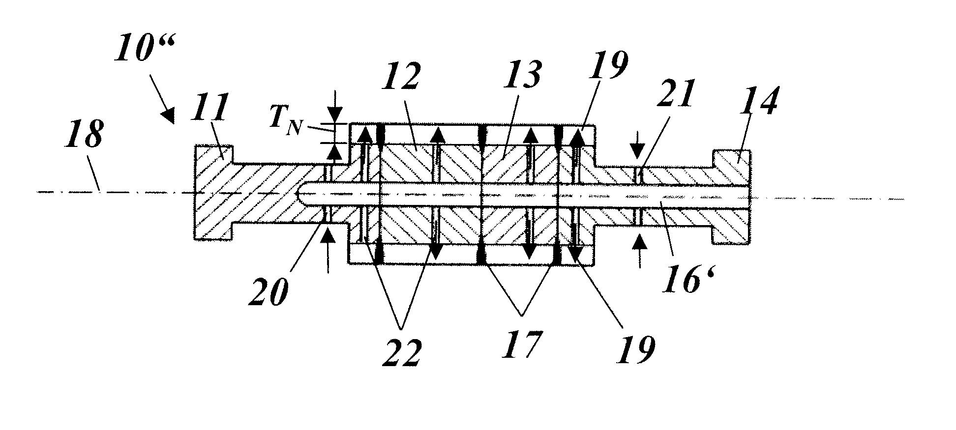
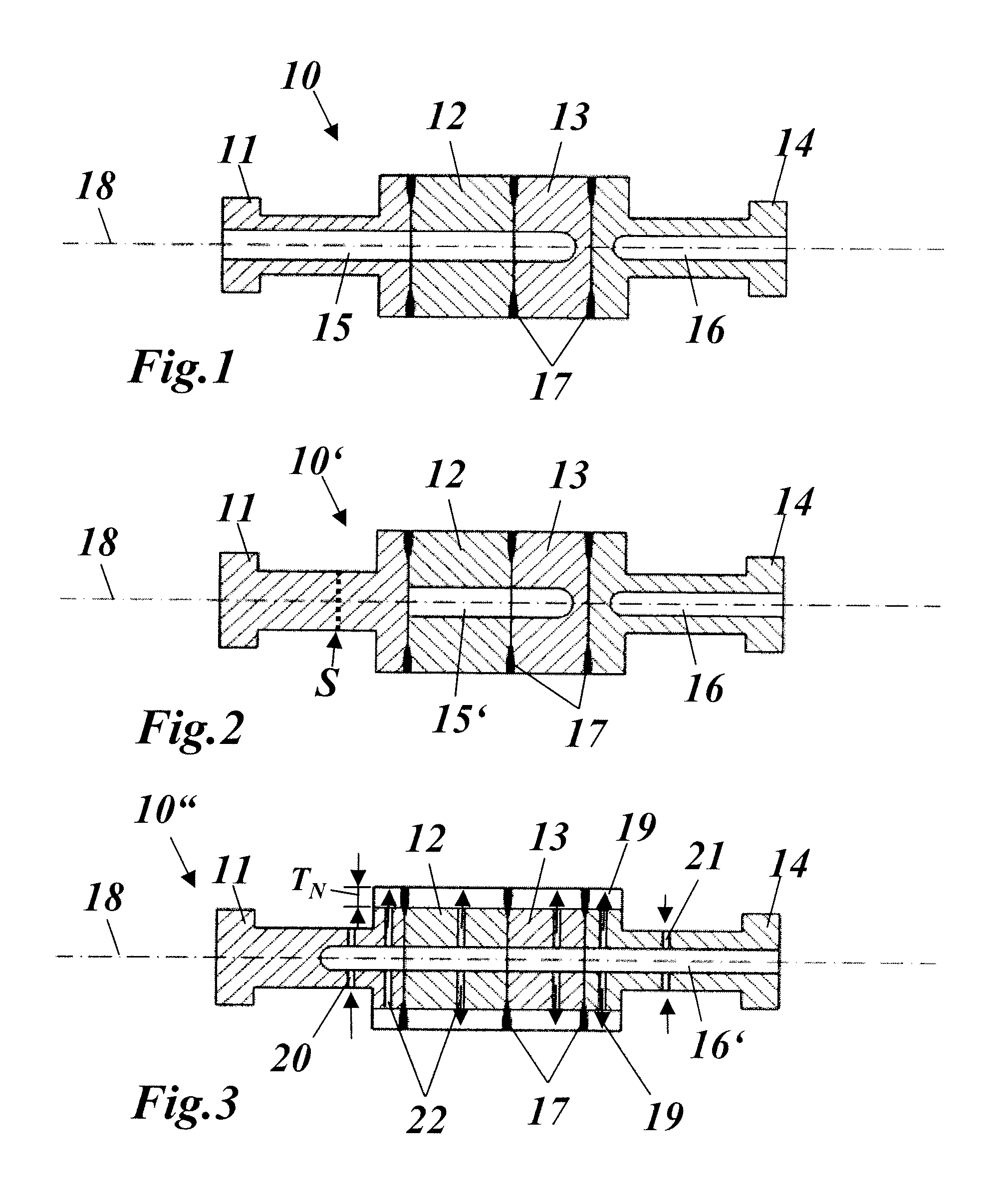
[0038]In FIGS. 1 to 3, different exemplary embodiments of a turbogenerator rotor embodying principles of the invention are represented in longitudinal section.

[0039]The rotor 10 of FIG. 1 is assembled from two disks 12, 13 which are concentrically arranged in the direction of the rotor axis 18 and welded to one another and welded at the ends in each case to a shaft end 11 or 14. The disks 12, 13 and the shaft ends 11, 14 together represent the rotor elements, which are formed essentially cylindrical. The connecting faces of the rotor elements 11, . . . , 14, by which the rotor elements are interconnected (welded), are oriented perpendicularly to the rotor axis 18 and formed essentially flat.

[0040]The rotor body of the rotor 10 is formed by the two disks 12, 13 and inner sections of the two shaft ends 11, 14. It is characterized by an outside diameter which is enlarged in relation to the shaft ends 11, 14. The winding slots (19 in FIG. 3), which accommodate the rotor winding, are sit...


PUM

PropertyMeasurementUnit
Angleaaaaaaaaaa
Diameteraaaaaaaaaa
Lengthaaaaaaaaaa

Abstract

A rotor (10) for a generator, especially for a turbogenerator, is assembled from a plurality of separate rotor elements (11, 12) which are arranged one behind the other in the rotor axis (18), wherein the rotor elements (11, 12) abut on connecting faces and are welded to one another, forming circular weld seams (17) which concentrically encompass in each case an annular central gap (37) with a predetermined gap width. In order to achieve a maximum magnetically active volume with mechanical stresses which are as low as possible, on the outer circumference of the gap (37) the gap merges into a widening cavity (38) which is adjacent to the weld seam (17).

Description

[0001]This application claims priority under 35 U.S.C. § 119 to Swiss Application No. 00350 / 07, filed 2 Mar. 2007, the entirety of which is incorporated by reference herein.BACKGROUND[0002]1. Field of Endeavor[0003]The present invention relates to generators for generating electrical energy, and more specifically to turbogenerator rotors.[0004]2. Brief Description of the Related Art[0005]For a long time it has been known to produce rotors of large turbomachines, such as steam turbines or gas turbines, from individual rotor elements which are welded together to form a unit (see, for example, EP A1-0 604 754). As a result of this, it is possible, inter alia, to produce the thermally differently stressed sections of the rotor from different materials, and to optimize the sections of the rotor with regard to cost and stability. Also, in the case of materials purchasing, it is simpler to procure comparatively small disk-shaped elements than to procure a specially manufactured and formed ...

Claims


Application Information

Patent Timeline
IPC IPC(8): H02K1/22H02K1/32H02K15/02H02K1/26
CPCB23K33/006B23K2201/001B23K2201/04F01D5/063Y10T29/49012H02K1/32F05D2240/60F05D2230/232F05D2300/507H02K1/26B23K2101/001B23K2101/04
Inventor ROTZINGER, RALFVOGT, MARKUSJOHO, REINHARD
Owner GENERAL ELECTRIC TECH GMBH
Why Eureka
Try Eureka