
Downhole pilot bit and reamer with maximized mud motor dimensions

Inactive Publication Date: 2009-07-21
BROUSSARD EDWIN J +1
View PDF13 Cites 42 Cited by
  • Summary
  • Abstract
  • Description
  • Claims
  • Application Information

AI Technical Summary

Benefits of technology

[0014]It is another object of the invention to provide a drilling system that will prevent damage to the drilling system when the diameter of the well casing is reduced.
[0022]In one preferred embodiment, the pilot bit is offset relative to the center of the end of the drill housing. This will provide for increased tangential speed at the point of impact between the pilot bit and the formation at the point opposite the center of the end of the housing. This should increase ROP as well as increase the size of the pilot hole.

Problems solved by technology

However, surface imparted torque has its limits.
Too much torque and—rather than turning the bit—the drill string itself will twist in two.
The pilot bit is often the limiting step in drilling.
That is, when the pilot bit moves through a formation, the rock surrounding the path of the bit is shattered or at least substantially weakened by the passage of the pilot bit.
The operation of drilling systems is expensive.
Much of the equipment is rented by the day, and delays can substantially increase the cost of the well.
This can be very time consuming and thus very expensive.

Method used


Image

  • Downhole pilot bit and reamer with maximized mud motor dimensions
  • Downhole pilot bit and reamer with maximized mud motor dimensions
  • Downhole pilot bit and reamer with maximized mud motor dimensions

Examples


Embodiment Construction

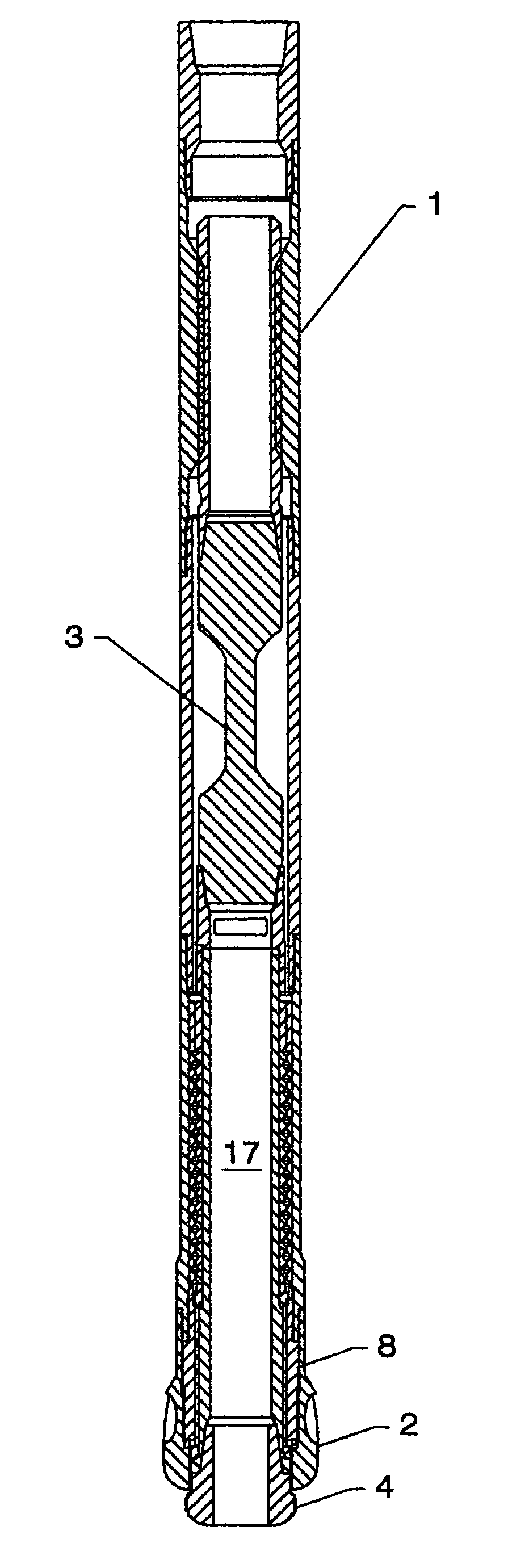
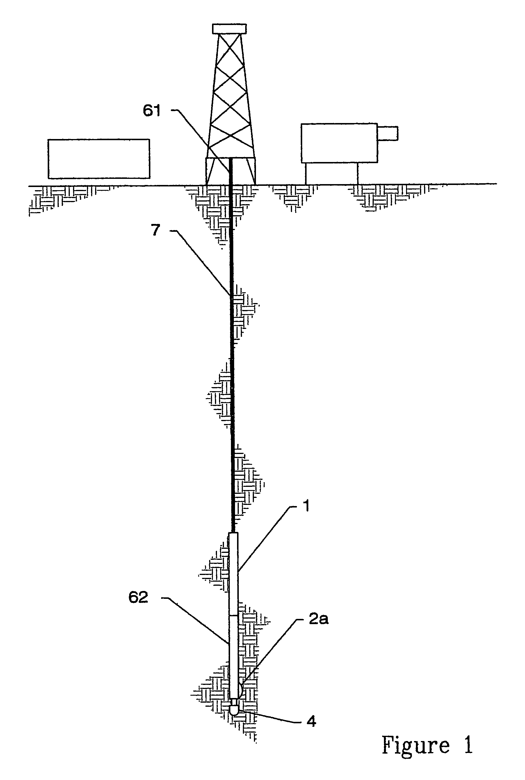
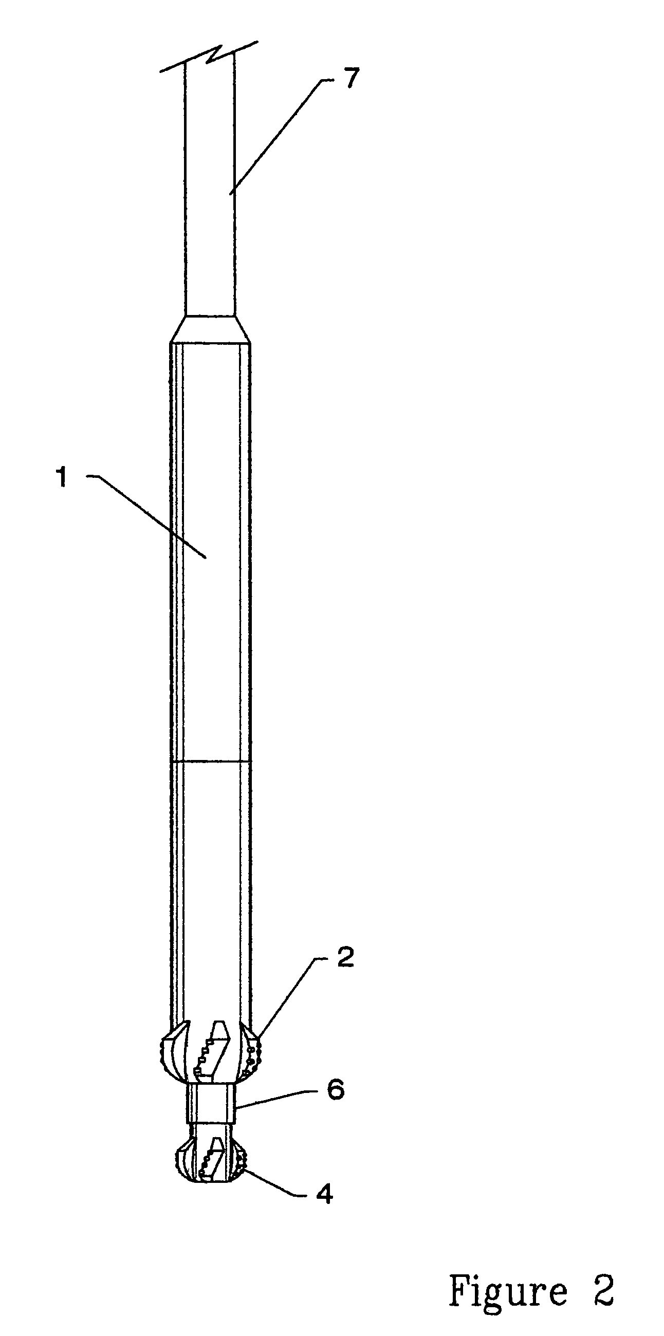
[0036]One embodiment of the invention involves the combination of a drill housing 1 having a reamer 2, which may be a bi-center bit 2a, with a mud motor 3 and a pilot bit 4. Housing 1 and its attached reamer 2 are located at the bottom end 62 of drill string 7 and may be turned from the surface end 61 of drill string 7. Stabilizers 5 may be placed below and proximate to reamer 2, particularly when bi-center bit 2a is used. If reamer 2 were not included, stabilizer 5 would preferably be used in place of reamer 2. A spacing tube may be included between reamer 2 or bi-center bit 2a and mud motor 3. Drilling mud flows through the drill string 7 and some exits proximate to reamer 2. This mud lubricates reamer 2 and entrains cuttings. More drilling mud flows through one or more mud motors 3 which in turn drive pilot bit 4.

[0037]In the preferred embodiment, mud motor 3 has a 1:2 lobe assembly ratio, but other ratios may be used as desired. The clearance between the rotor and the stator may...


PUM


Abstract

A drilling unit containing a combined pilot bit and reamer. The drilling unit includes a housing containing a mud motor and a pilot bit extending from its distal end. A reamer is mounted to the housing. The mud motor turns the pilot bit while the reamer is turned either by the mud motor or as the drill string is rotated from the surface. The well bore is drilled and reamed in one pass.By positioning the reamer between the pilot bit and the mud motor, the mud motor must only pass through the larger reamer bore rather than the smaller pilot hole. This will allow larger mud motors to be used than would otherwise be possible.In one embodiment, the pilot bit is offset relative to the center of the end of the drill housing, providing increased tangential speed at the point of impact between the pilot bit and formation.

Description

CLAIM TO BENEFIT OF PROVISIONAL APPLICATION[0001]This application claims benefit of provisional application No. 60 / 486,523 which was filed on Jul. 10, 2003, and is hereby incorporated by reference in its entirety.BACKGROUND OF THE INVENTION[0002]1. Field of the Invention[0003]The invention relates to drilling bits in general and to combined pilot and reamer bits, in particular.[0004]2. Prior Art[0005]Torque is imparted to drill bits in one of two primary means. First, the entire drill string is turned from the surface. Second, “mud motors” (impeller driven shafts) are installed in the drill string near the bit. Drilling “mud” is pumped through the drill string, through the impeller, and out apertures on or near the pilot bit. The mud passing through the impeller turns the impeller which then turns the bit.[0006]The drilling mud serves several other purposes as well. Once the mud flows out of the drill string near the bit, it is pumped back to the surface of the well. As it is flowin...

Claims


Application Information

Patent Timeline
IPC IPC(8): E21B10/02E21B10/26
CPCE21B7/28E21B10/265
Inventor BROUSSARD, EDWIN J.SCHELLSTEDE, HERMAN J.
Owner BROUSSARD EDWIN J
Learn More