Motor controller of electric power steering device

a technology of electric power steering and motor controller, which is applied in the direction of motor/generator/converter stopper, dynamo-electric converter control, cycle, etc., can solve the problems of significant increase in voltage drop and power loss in the diode, reduced output of the motor, and reduced efficiency, so as to prevent the decrease of voltage and electric power loss, reduce power loss, and facilitate the selection of the element

Active Publication Date: 2008-09-04
JTEKT CORP
View PDF9 Cites 5 Cited by
  • Summary
  • Abstract
  • Description
  • Claims
  • Application Information

AI Technical Summary

Benefits of technology

[0008]According to an aspect of the invention, a motor controller of an electric power steering device includes a main power supply that supplies electric power to a motor of the electric power steering device; an auxiliary power supply that is able to supply electric power to the motor; a diode that is provided in an electric path through which electric power is supplied from the main power supply to the motor, the diode preventing a sneak current from the auxiliary power supply to the main power supply; a semiconductor switching element that is connected in parallel with the diode; and a control / driving circuit that turns on the semiconductor switching element when electric power is supplied from the main power supply to the motor, and turns off the semiconductor switching element when electric power is supplied to the motor by using the auxiliary power supply.
[0009]In the motor controller of the electric power steering device configured in such a manner, when electric power is supplied from only the main power supply, the semiconductor switching element is turned on and is connected in parallel with the diode. Accordingly, most of currents flowing from the main power supply to the motor flow into the semiconductor switching element of which the on-resistance is lower than the diode. Therefore, it is possible to prevent a decrease in voltage and a loss in electric power.
[0010]In the motor controller of the electric power steering device, the semiconductor switching element is an N-channel MOS-FET.
[0011]Since the on-resistance of the N-channel MOS-FET is small, the N-channel MOS-FET is suitable for reducing a power loss. Further, since various kinds of N-channel MOS-FETs are available, selection of the element is conducted easily, and the price thereof can be kept low.
[0012]In the motor controller of the electric power steering device, another semiconductor switching element is provided in an electric path through which electric power is supplied from the auxiliary power supply to the motor, and the control / driving circuit causes one of the semiconductor switching elements to gradually transit from the on-state to the off-state and causes the other to gradually transit from the off-state to the on-state, in accordance with PWM control.
[0013]In this case, the state inversion from the on-state to the off-state and the state inversion from the off-state to the on-state are gradually performed by the PWM control. Therefore, it is possible to prevent a rapid change in voltage when the power supplies are switched, thereby preventing a variation in torque of the motor.

Problems solved by technology

In this case, since a current value is large (several tens to more than 100 amperes), a voltage drop and a power loss in the diode significantly increase and the efficiency decreases.
Therefore, the output of the motor is reduced, and a reduction in assist force occurs, which may degrade a steering feeling.
However, the high speed responsibility and durability of such a mechanical contact may not be satisfactory.

Method used


Image

  • Motor controller of electric power steering device
  • Motor controller of electric power steering device
  • Motor controller of electric power steering device

Examples


Embodiment Construction

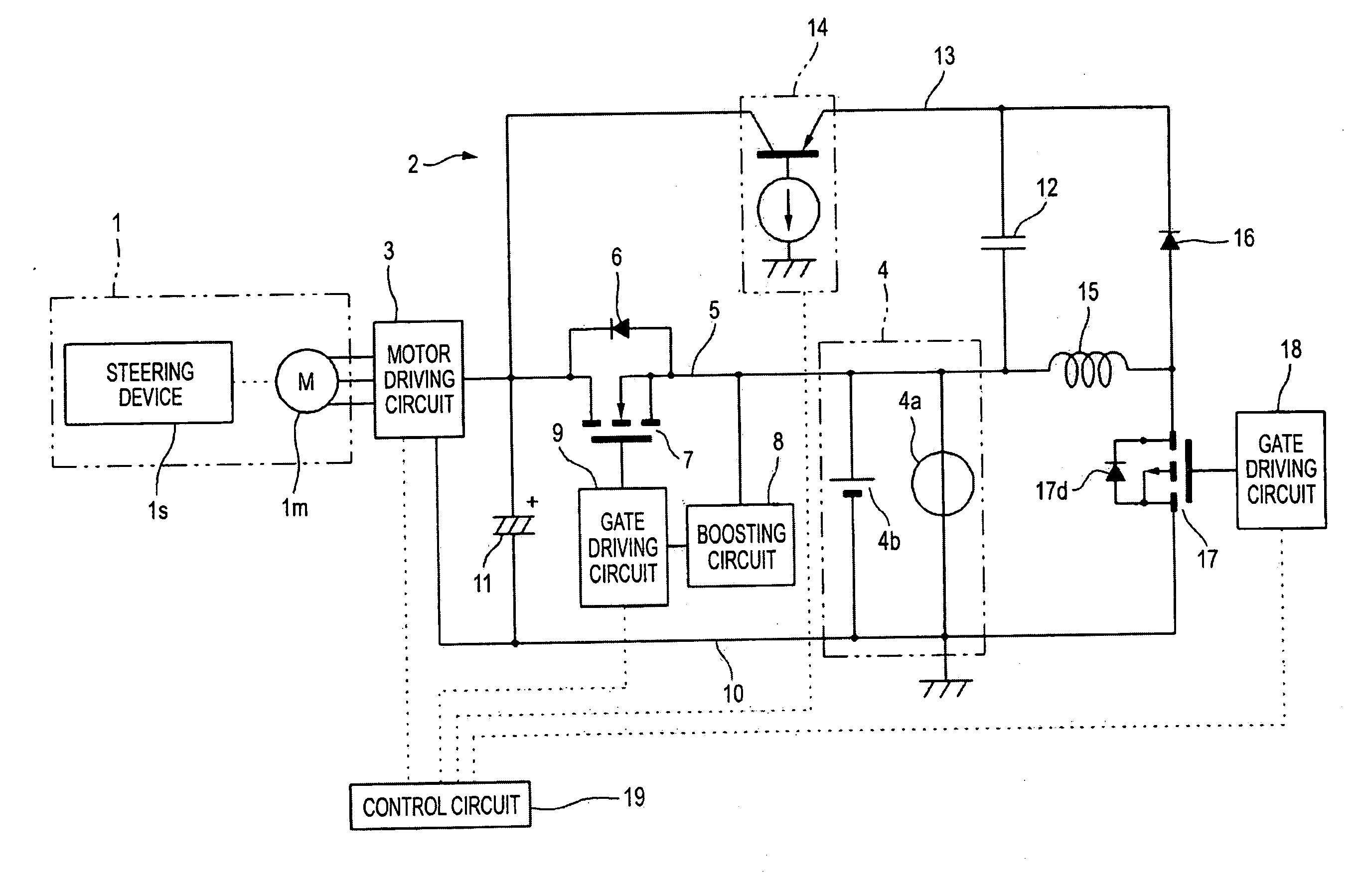
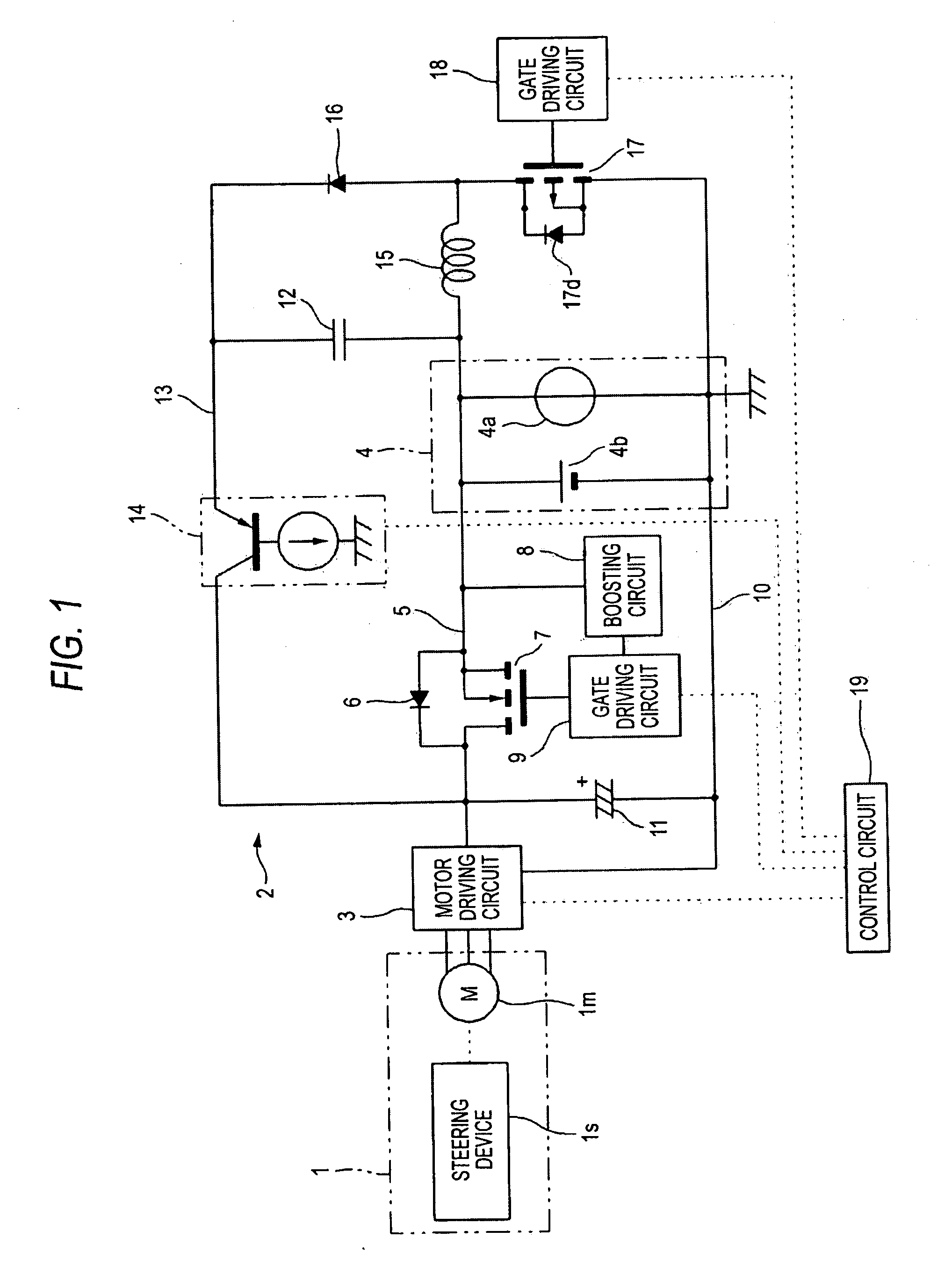
[0020]FIG. 1 is a circuit diagram showing a motor controller 2 of an electric power steering device 1 according to a first embodiment of the invention. In FIG. 1, a steering assist force is applied to a steering device is of a vehicle by a motor 1m, and a motor driving circuit 3 supplies power to the motor 1m. A main power supply 4 is composed of an in-vehicle battery 4b and an alternator 4a. In the middle of a non-ground-side electric path 5 leading the main power supply 4 to the motor driving circuit 3, a diode 6 is disposed so as to set the direction from the main power supply 4 to the motor driving circuit 3 as forward direction.

[0021]Further, an N-channel MOS-FET 7 serving as a semiconductor switching element is connected in parallel with the diode 6, such that the N-channel MOS-FET has a source connected to the side of the main power supply 4 and a drain connected to the side of the motor driving circuit 3. The source of the MOS-FET 7 is connected to a boosting circuit (bootst...


PUM


Abstract

In a motor controller which supplies electric power to a motor of an electric power steering device from a main power supply and an auxiliary power supply, an N-channel MOS-FET is connected in parallel with a diode which is provided to prevent a sneak current from the auxiliary power supply to the main power supply. When electric power is supplied to the motor from the main power supply, the MOS-FET is turned on. Then, most of currents flow into the MOS-FET such that a power loss is reduced and a reduction in efficiency is prevented. The MOS-FET has high speed responsibility and excellent durability.

Description

SUMMARY OF THE INVENTION[0001]1. Field of the Invention[0002]The present invention relates to a motor controller of an electric power steering device which is mounted in vehicles such as automobiles.[0003]2. Related Art[0004]As a required steering assist force is increased, an electric power steering device needs to flow a high current into a motor. Electric power may be insufficient if it is supplied only from an in-vehicle battery. Therefore, although electric power is supplied from the in-vehicle battery as a main power supply normally, a terminal voltage of the main power supply may decrease due to an increase in load. In such a case, conventionally, there has been proposed a configuration in which electric power is supplied from an auxiliary power supply, which has previously stored electric power, such that the burden of the main power supply is reduced. (See JP-A-2006-282121.) In case that the auxiliary power supply is used, a diode is inserted into an electric path such that...

Claims


Application Information

Patent Timeline
Patent Type & Authority Applications(United States)
IPC IPC(8): H02P4/00
CPCB62D5/0475B62D5/0457
Inventor NAGASE, SHIGEKI
Owner JTEKT CORP
Why Eureka
Try Eureka