

Rotating machinery controller
a technology of rotating machinery and controllers, which is applied in the direction of electronic commutators, motors/generators/converter stoppers, dynamo-electric converter control, etc., can solve the problems of excessive current and inability to feedback control the actual current of rotating machinery, and achieve the effect of reducing power loss and increasing voltage utilization factor
- Summary
- Abstract
- Description
- Claims
- Application Information
AI Technical Summary
Benefits of technology
Problems solved by technology
Method used
Image

Examples
first embodiment
[0082]A first preferred embodiment of the present invention will be described hereinbelow in detail with reference to the accompanying sheets of drawings, wherein a rotating machinery controller according to the present invention is shown as applied to a controller for a three-phase motor mountable to a hybrid car.
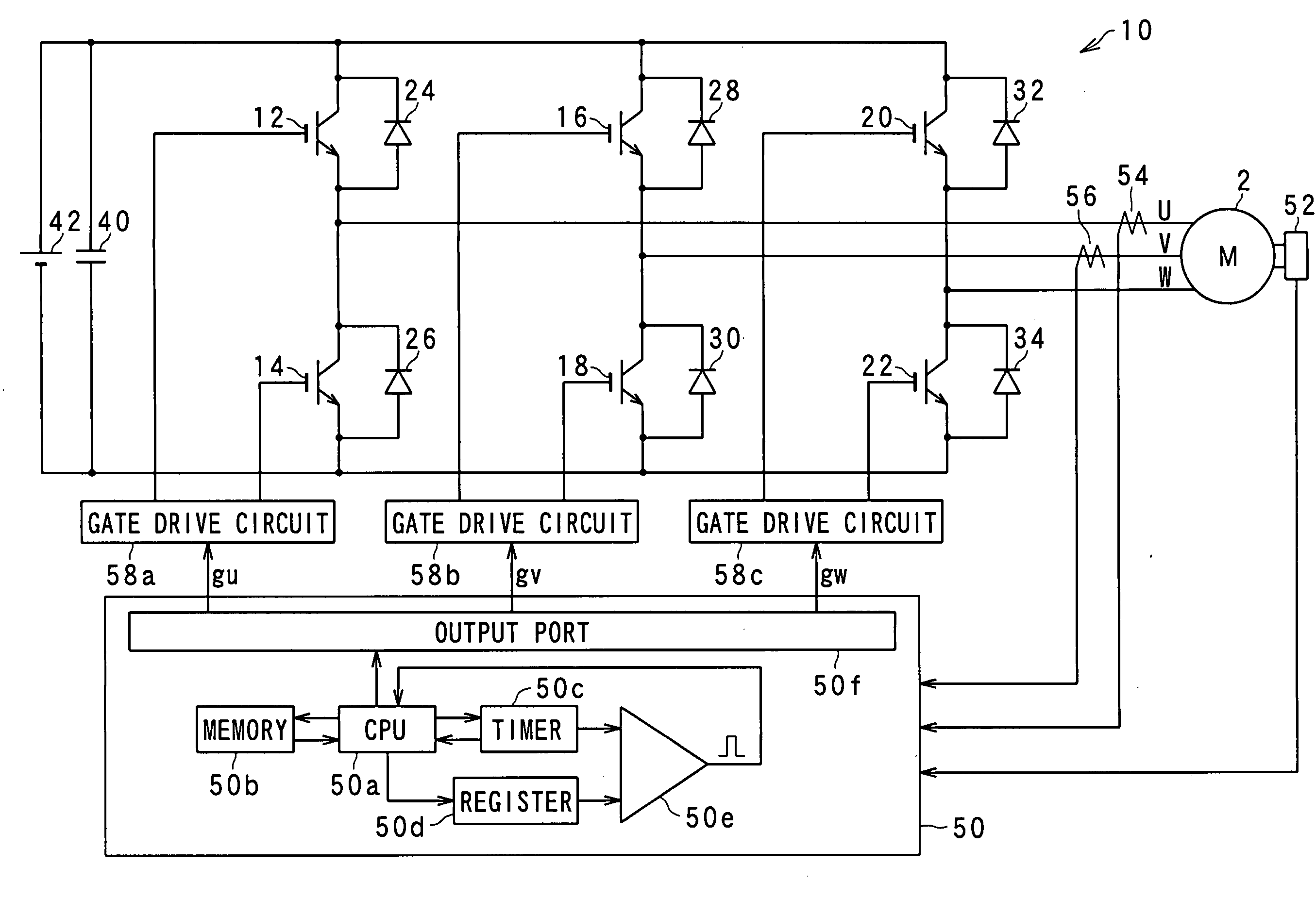
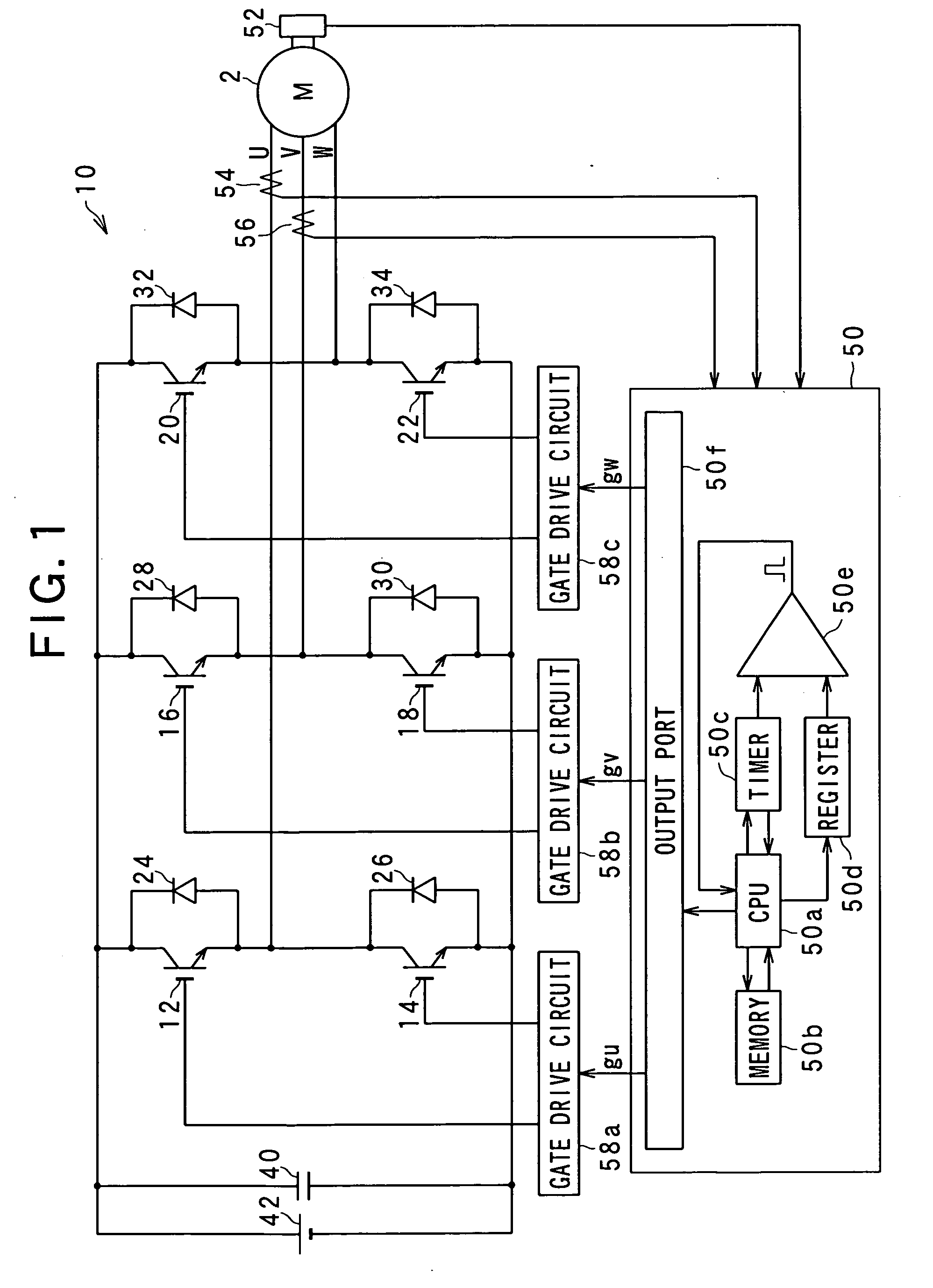
[0083]FIG. 1 shows the general configuration of the three-phase motor and the controller used in combination. As shown in FIG. 1, the three-phase motor comprises a DC brushless motor 2 having three phases (U-phase, V-phase and W-phase) connected to an inverter 10. The inverter 10 comprises a three-phase inverter having three pairs of switching devices 12 and 14, 16 and 18, and 20 and 22 connected in parallel and provided each for a respective one of the three phases U, V and W. The inverter 10 also includes diodes 24, 26, 28, 30, 32 and 34 connected in inverse-parallel to the respective switching devices 12, 14, 16, 18, 20 and 22. The switching devices 12 and 14 are connec...
second embodiment
[0142]A second preferred embodiment of the present invention will be described below in detail while focusing attention to the differences from the first embodiment.
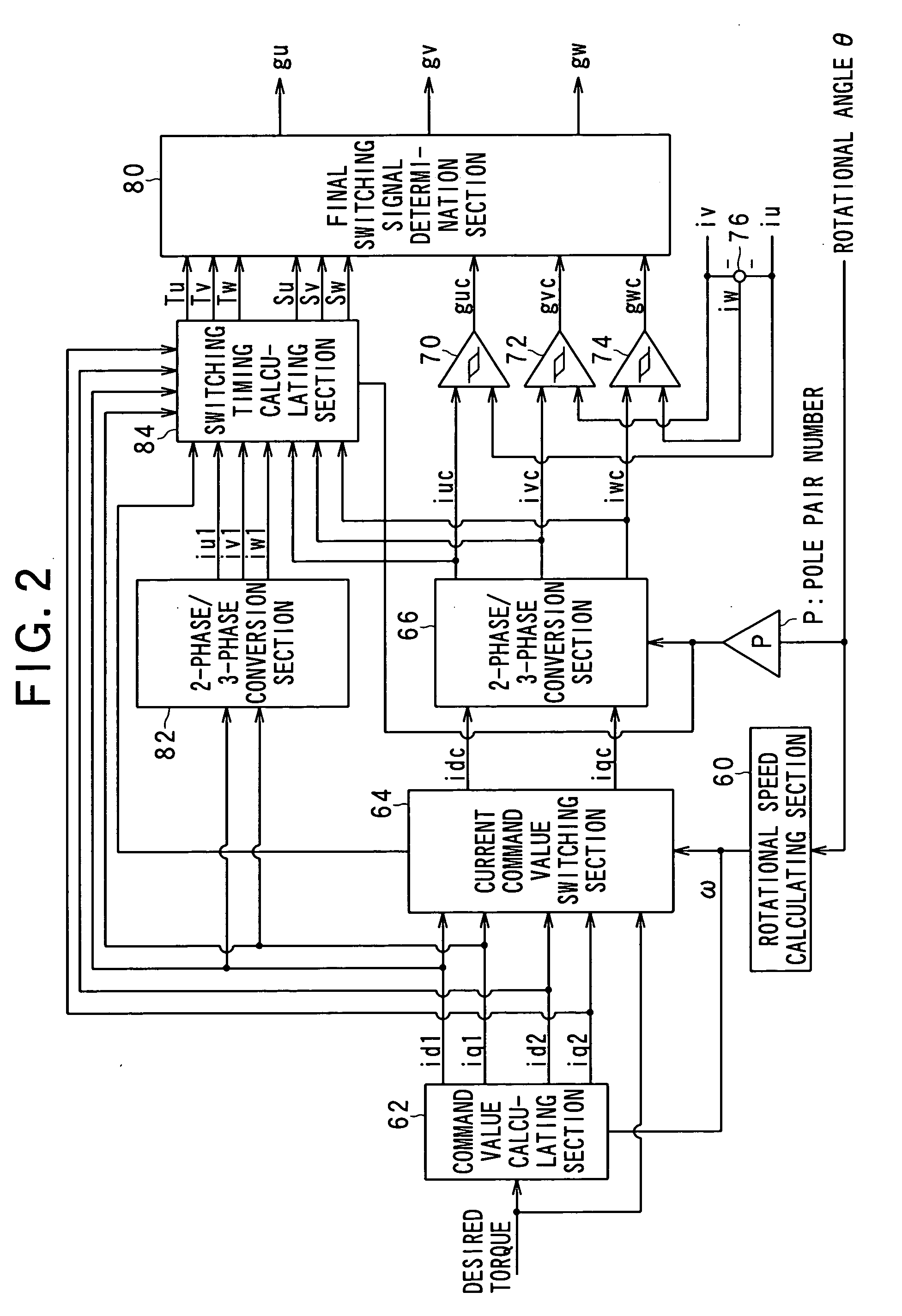
[0143]In this embodiment, the second command currents iuc2, ivc2, iwc2 and the first command currents iuc1, ivc1, iwc1 at the next control time are calculated by approximation using up to the second degree terms of Taylor's series. It should be note that derivative values of the second order of these command currents can be obtained by subjecting the current vectors (id, iq) into two-phase / three-phase conversion and multiplied by −w×w. FIG. 17 shows a calculation process to obtain increments Δiuc2, Δivc2, Δiwc2 of the second command currents iuc2, ivc2, iwc2 and increments Δiuc1, Δivc1, Δiwc1 of the first command currents iuc1, ivc1, iwc1 according to the second embodiment of the present invention.
[0144]As shown in FIG. 17, a multiplier 100 reverses the sign of a q-axis component of the dq-axis current vectors (id, iq) a...
third embodiment
[0147]A third preferred embodiment of the present invention will be described below in detail while focusing attention to the differences from the first embodiment.
[0148]FIG. 18 shows a calculation process for estimating the second command currents iuc2, ivc2, iwc2 and first command currents iuc1, ivc1, iwc1 at the next control time according to the third embodiment.
[0149]As shown in FIG. 18, the current vectors (id, iq) are converted by a two-phase / three-phase conversion section 130 into three-phase current vectors. In this instance, an electrical angle used for such phase conversion consists of an angle which is lead the current electrical angle θ×p by a phase angle wT corresponding to an angular distance from the current control time to the next control time. With this arrangement, it is possible to calculate estimated values iuc2̂, ivc2̂, iwc2̂ of the second command currents at the next control time and estimated values iuc1̂, ivc1̂, iwc1̂ of the first command currents at the ne...
PUM
 Abstract
Description
Claims
Application Information