Magnetic Impedance Measurement Device

Inactive Publication Date: 2008-09-04
NATIONAL UNIVERSITY
View PDF6 Cites 44 Cited by
  • Summary
  • Abstract
  • Description
  • Claims
  • Application Information

AI Technical Summary

Benefits of technology

[0065]According to the first aspect of the present invention, an induced current can be generated in the test object by means of the apply coil. Hereinafter the central axis of the apply coil will be defined as the z axis, while the coil face will be defined as the xy plane defined by the orthogonal x and y axes. The x and y components of the component of the magnetic field parallel to the face of the apply coil of a magnetic field further generated from the induced current are each measured by means of detecting magnetic sensors. With respect to the magnetic distribution of the tangential component, the intensity distribution of the tangential component equivalently corresponds to the current distribution, because the intensity of the tangential component is large directly above the current. In addition, the magnetic field generated from the induced current has the same phase as that of the current. In such a way, a signal corresponding a local impedance characteristic of the test object can be obtained from the measured intensity and phase of the tangential component of the magnetic field. Further, since changes in the dielectric constant or the electrical conductivity of various test objects in response to a frequency change can be measured due to the variable frequency, it is possible to measure a change of the impedance in response to the frequency change. As for the magnetic field generated by the apply coil, the intensity of the component parallel to the apply coil axis, i.e. the z component, is the largest, while the x and y components are the smallest. Accordingly, the magnetic field generated by the apply coil entering into the magnetic sensor is quite large as compared to the magnetic field generated from the test object, with the result that it is necessary in the conventional art to provide a cancel coil for canceling the magnetic field from the apply coil near the magnetic sensor. In the present invention, however, because it is the x and y components with the smallest intensity of the magnetic field from the apply coil that are to be measured, there is no need for providing a cancel coil, which leads to a simpler configuration.
[0066]According to the second aspect of the present invention, in the case of measuring a magnetic response characteristic of the test object, the magnetic change varies substantially, depending on the distance between the apply coil and

Problems solved by technology

Moreover, with the method of directly measuring the vectorial components to estimate the current source, phase changes due to influences of the applied magnetic field or local impedance characteristics of the magnetic field generated from the test object cannot be measured because various interfering factors are not eliminated during a measurement.
Further, with the arrangement including a coil provided inside the apply coil for detecting the horizontal component in the eddy current flaw detection, measurement is problematically made only of a weak part of the eddy curre

Method used


Image

  • Magnetic Impedance Measurement Device
  • Magnetic Impedance Measurement Device
  • Magnetic Impedance Measurement Device

Examples


Example

Embodiment 1

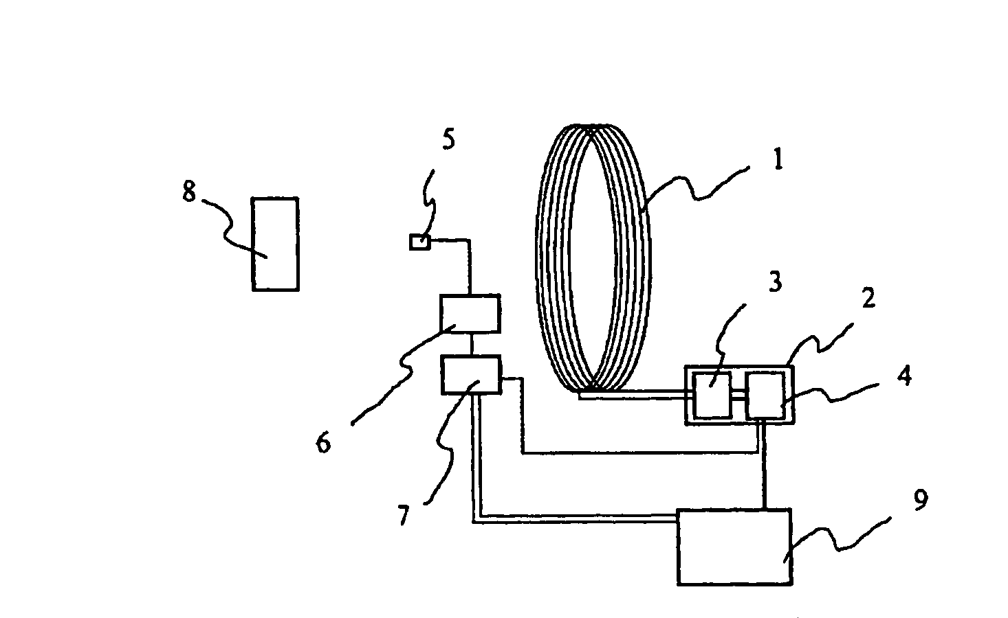
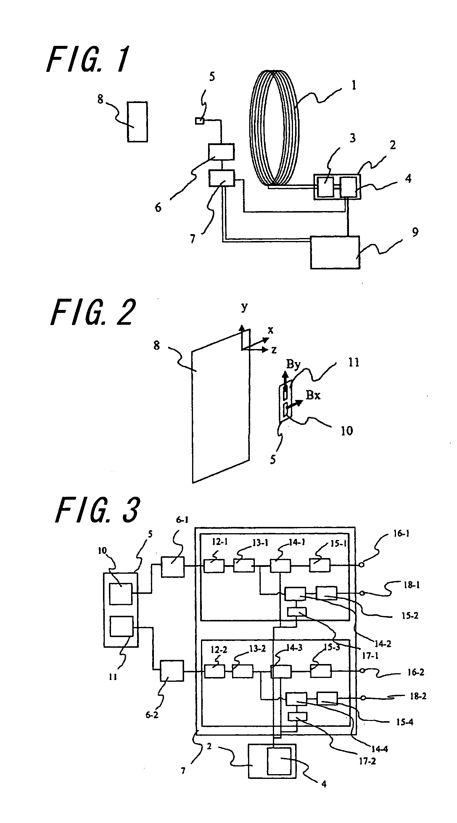
[0136]FIG. 1 is a schematic diagram showing a basic configuration of a magnetic impedance measurement device according to the present invention. A magnetic field is applied to the test object 8 by means of an apply coil 8. A power source 2 for the apply coil is adapted to change the frequency of the applied magnetic field by means of an oscillator 4. A current source 3 is driven with this signal to apply an alternate current to the apply coil 1. An induced current is generated in the test object 8 by the applied magnetic field and the induced current in turn generates another magnetic field. This magnetic field generated from the induced current is detected with a pair of magnetic sensor means 5 comprising magnetoresistive sensors. Here the coil face of the apply coil will be defined as the xy plane, while the central axis of the coil will be defined as the z axis. The one pair of magnetic sensor means 5 is provided, as shown in FIG. 2, with a magnetic sensor 10 for Bx a...

Example

Embodiment 2

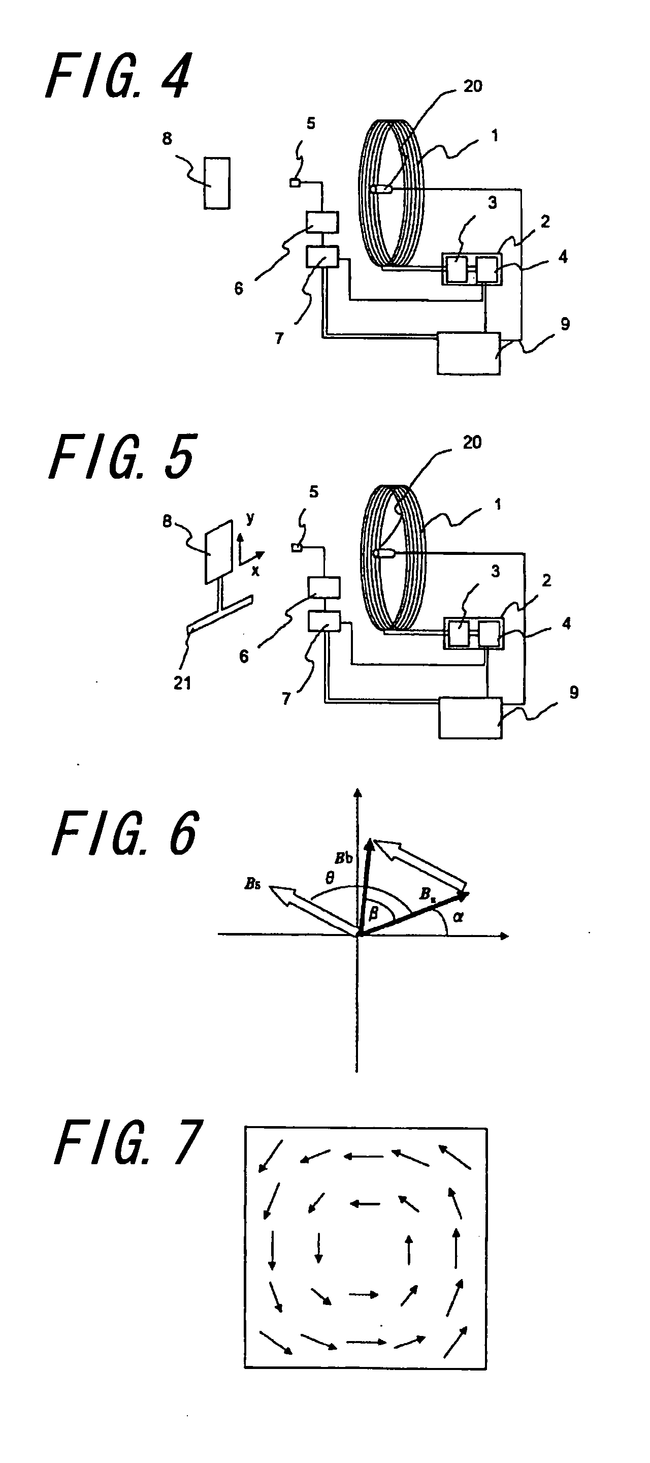
[0139]FIG. 4 is a schematic diagram showing a basic configuration of the magnetic impedance measurement device according to a second embodiment of the present invention. In embodiment 2, there is provided a distance measurement means 20 for the purpose of determining the positions of the test object 8 and the apply coil 1. The distance measurement means 20 may be placed anywhere, either in proximity to the apply coil 1 or in proximity to the one pair of the magnetic sensor means 5, as long as the relative distances of the distance measurement means 8 with respect to the apply coil 1 and the pair of the magnetic sensor means 5 is known. Here a distance meter with the use of a laser beam is used as the distance measurement means. The magnetic response characteristic of the test object 8 with respect to the applied magnetic field varies depending on the distance from the apply coil 1, and also the intensity of the signal varies substantially depending on the distance from t...

Example

Embodiment 3

[0140]FIG. 5 is a schematic diagram showing a basic configuration of the magnetic impedance measurement device according to embodiment 3 of the present invention. Here the device according to embodiment 2 is provided with a scanning means 21 for the test object and the distance between the pair of the magnetic sensor means and the test object can be held constant by means of a distance measurement means and measurement can be made on the test object with a scanning movement. With this mechanism, the distribution of a magnetic field generated from an induced current of the test object can be measured by means. Further, it is possible to analyze the distribution of the induced current from the distribution of the magnetic field.

[0141]FIG. 6 is a pattern diagram of a basic processing method for an output from the magnetic sensor having been subjected to a lock-in phase detection. An output from the magnetic sensor in the absence of the test object is defined as Ba. Because ...


PUM


Abstract

The distribution of the impedance characteristic of a test object is detected by applying an alternate magnetic field of a low frequency to the test object and measuring the induced current generated therefrom.
The present invention relates to a magnetic impedance measurement device comprising an apply coil for generating an alternate magnetic field of variable frequency, a power source for the apply coil, at least one magnetic sensor means comprising a pair of magnetic sensors for detecting orthogonal vector components of a magnetic field generated from a test object, the vector components being parallel to the face of the apply coil, a measurement means for the magnetic sensor for measuring a detected signal from said magnetic sensor mean, the measurement means being located at a distance from the face of said apply coil and facing said test object, a lock-in amplifier circuit for detecting from an output of said measurement means a signal having the same frequency as the frequency of said apply coil and an analysis means for analyzing intensity and phase changes of an output of said magnetic sensor means with the use of an output signal of said lock-in amplifier circuit.

Description

FIELD OF THE INVENTION[0001]The present invention relates to a device for applying an alternate magnetic field to a test object and detecting a response characteristic thereof using a magnetic sensor.BACKGROUND OF THE INVENTION[0002]A metal detector is known as a device for applying an alternate magnetic field to examine the response characteristics. The metal detector comprises a search coil that generates an alternate magnetic field to generate an eddy current on a metal surface of the test object, which in turn generates a magnetic field repulsive to the applied magnetic field. Since this magnetic field changes an electromotive force in response to changes in the magnetic flux penetrating through the search coil, as may be represented using Faraday's law of electromagnetic induction, existence of metal can be detected by measuring the changes in a signal. Also known are methods of nondestructive inspection such as a method for inspecting a defect in a steel pipe or a wire rope by...

Claims


Application Information

Patent Timeline
IPC IPC(8): G01N27/72
CPCG01N27/72G01R33/12G01R33/063
Inventor TSUKADA, KEIJIKIWA, TOSHIHIKO
Owner NATIONAL UNIVERSITY
Why Eureka
Try Eureka