Piezoelectric drive device and electronic device

a drive device and electronic device technology, applied in the field of piezoelectric drives, can solve the problems of inaccurate display position of hands, increased power consumption of ultrasonic drive devices, and shift of hands, and achieve the effect of low power

Inactive Publication Date: 2008-09-04
SEIKO EPSON CORP
View PDF3 Cites 16 Cited by
  • Summary
  • Abstract
  • Description
  • Claims
  • Application Information

AI Technical Summary

Benefits of technology

[0017]In this aspect of the invention driving the rotor makes the driven body to rotate, and the rotation limiting device limits rotation of the driven body to a constant angle. As a result, even if rotation of the driven body is not constant relative to a given amount the piezoelectric actuator is driven, the angle of rotation of the driven body is limited to a constant angle by the rotation limiting device once the driven body has rotated a specific angle, and rotation of the driven body is therefore constant. Overrun of the driven body that is rotated by the piezoelectric actuator can therefore be prevented, the precision of the angle of rotation of the driven body can be improved without needing to precisely control the angle of rotation of the rotor, and the display precision of the hand or other indicator means that is rotated by the driven body can be improved.
[0064]Because the time information display unit such as the hands of the timepiece is driven by a piezoelectric drive device, this aspect of the invention prevents driving the hands from being affected by magnetic fields, and enables driving the hands of the time information display unit with low power.

Problems solved by technology

The inertial moment is thus determined by the arrangement and form of the wheel train and hands, for example, the acceleration time of the rotor increases as the moment of inertia rises, the drive signal must therefore be applied to the vibrator (oscillator) longer, and power consumption by the ultrasonic drive device increases.
Therefore, if a piezoelectric drive device using a piezoelectric actuator cannot drive in steps of a constant angle, the position of the hands will shift and this is a major problem.
This makes the display position of the hand inaccurate when a timepiece hand, for example, is attached to the driven body.
Furthermore, if an elastic device is provided but there is no initial elastic deformation, the driven body vibrates easily when an external shock is applied even if rotation of the rotor is limited when the piezoelectric actuator is stopped because the elastic energy of the elastic device is not applied to the driven body.
However, if the inertial moment of the rotating system downstream from the driven body is large, such as when the rotating target object downstream from the driven body is large or the transmission path after the driven body is composed of a plurality of driven bodies, the driven body does not start rotating immediately with rotation of the rotor, and problems can result.
Therefore, if the driven body does not start rotating even though the rotor has rotated the distance of one cycle, the elastic device cannot be elastically deformed before the rotor rotates the amount of one cycle, and the inertia of the driven body is applied to the rotor.
A problem with a reverse escapement is that the load on the piezoelectric actuator is high.
More specifically, unlike the escapement of a mechanical timepiece, a reverse escapement transmits drive power from the pallet fork to the escape wheel, and there is a significant drop in drive power transmission efficiency compared with transmission by means of gear wheels.
As a result, the load on the piezoelectric actuator increases, drive speed drops, and more time is needed to advance the desired number of steps.

Method used


Image

  • Piezoelectric drive device and electronic device
  • Piezoelectric drive device and electronic device
  • Piezoelectric drive device and electronic device

Examples


embodiment 1

[0092]A first embodiment of the invention is described next with reference to the accompanying figures.

[0093]Note that parts in the second and later embodiments that are the same as or have the same function as parts in the first embodiment are identified by the same reference numerals, and further description thereof is omitted or simplified.

General Configuration

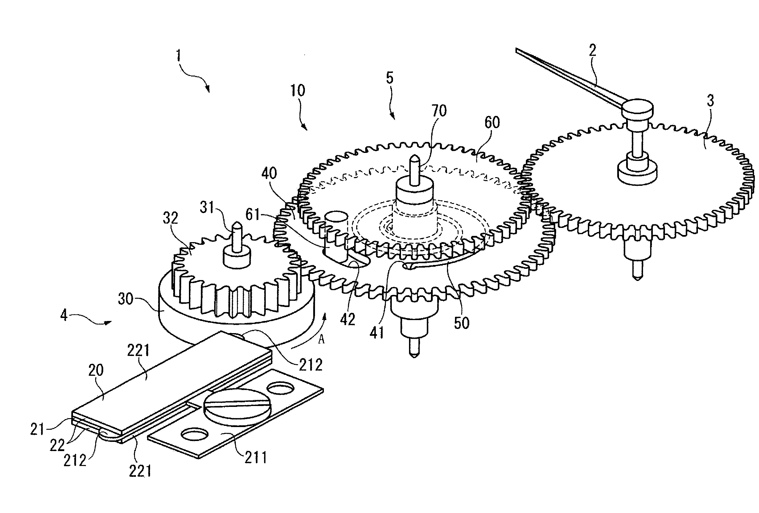
[0094]FIG. 6 and FIG. 7 are an oblique view and a plan view showing the drive mechanism of a hand 2 in a timepiece (electric device) 1 according to a first embodiment of the invention. The timepiece 1 has a timekeeping unit 200 inside a case member not shown, a time information display unit that displays the time kept by the timekeeping unit 200 by means of the hand 2, and a drive mechanism for the hand 2. The drive mechanism includes mechanisms for driving a plurality of hands, and includes the movement shown in FIG. 8). A piezoelectric drive device 10 is used to operate the drive mechanism of the hand 2. More specifically...

embodiment 2

[0190]A piezoelectric drive device 10A in a timepiece according to a second embodiment of the invention is described next with reference to FIG. 11 to FIG. 14.

[0191]FIG. 11 is a plan view of the piezoelectric drive device 10A in this timepiece. FIG. 12 to FIG. 14 are longitudinal section views of the piezoelectric drive device 10A. FIG. 12 is a section view of the transmission path connecting the rotor (rotor ring 30, rotor pinion 32, and rotor wheel 33), intermediate wheel 6, and rotor transmission wheel 5A. FIG. 13 is a section view of the transmission path connecting the rotor, pallet fork 8, and rotor transmission wheel 5A in FIG. 11. FIG. 14 is a section view of the piezoelectric actuator 4A including a vibrator 20A and rotor in FIG. 11.

[0192]The piezoelectric drive device 10A differs from the piezoelectric drive device 10 in the first embodiment by having an escape wheel 60A corresponding to a second rotor transmission wheel, and limiting rotation of the escape wheel 60A to a ...

embodiment 3

[0233]A piezoelectric drive device 10B in a timepiece according to a third embodiment of the invention is described next with reference to FIG. 15 to FIG. 18.

[0234]FIG. 15 is a plan view of the piezoelectric drive device 10B in this timepiece. FIG. 16 and FIG. 17 are longitudinal section views of the piezoelectric drive device 10B. FIG. 18 is a plan view describing driving the piezoelectric drive device 10B.

[0235]This piezoelectric drive device 10B differs from the piezoelectric drive device 10A of the second embodiment by using a follower 60B instead of the escape wheel 60A, and using a drive wheel 9 instead of the pallet fork 8 as a rotation limiting device, and is otherwise the same.

[0236]The piezoelectric drive device 10B includes an intermediate wheel 6A that meshes with and is rotated by the rotor ring 30A, the drive wheel 9 that is rotated by the intermediate wheel 6A, and the rotor transmission wheel 5B.

[0237]The rotor ring 30A is fixed with the rotor wheel 33 to the rotor a...


PUM


Abstract

A piezoelectric drive device has a piezoelectric actuator that has a vibrator with a piezoelectric element, and a rotor that is rotated by the vibrator, an elastic device that can store the rotational energy of the rotor as elastic energy, and a driven body that is rotated by the elastic energy stored by the elastic device.

Description

CROSS-REFERENCE TO THE RELATED APPLICATIONS[0001]This application claims priority to Japanese Patent Application Nos. 2007-051312 and 2007-278763. The entire disclosure of Japanese Patent Application No. 2007-051312 and 2007-278763 is hereby incorporated herein by reference.BACKGROUND[0002]1. Technical Field[0003]The present invention relates to a piezoelectric drive device having a piezoelectric actuator, and to an electronic device.[0004]2. Related Art[0005]Ultrasonic drive devices that use piezoelectric elements resistant to the effects of magnetism and are used as a drive device for driving the hands in a timepiece are known from the literature. Japanese Laid-Open Patent Publication JP-10-290579-A discloses such device as an example.[0006]While the rotor starts rotating when a high frequency voltage (drive signal) is applied to the vibrator in order to start the ultrasonic drive device disclosed in JP-A-H10-290579 from a stopped state, a certain amount of time (acceleration time...

Claims


Application Information

Patent Timeline
Patent Type & Authority Applications(United States)
IPC IPC(8): G04C3/12H02N2/00
CPCG04C3/12H02N2/123H02N2/103H02N2/004
Inventor NAGAO, SHOICHI
Owner SEIKO EPSON CORP
Why Eureka
Try Eureka