Method of Cleaning a Refractive Element and Optical Scanning Apparatus For Nearfield Optical Systems

a technology of optical scanning apparatus and refractive element, which is applied in the direction of instruments, mechanical recording, record information storage, etc., can solve the problems of system sensitive to small contaminants, slider colliding with the disc, and hydrodynamic air pressure, so as to reduce hydrodynamic air pressure, improve cleaning efficiency, and negatively affect the transmission of radiation

Inactive Publication Date: 2008-09-04
KONINKLIJKE PHILIPS ELECTRONICS NV
View PDF7 Cites 6 Cited by
  • Summary
  • Abstract
  • Description
  • Claims
  • Application Information

AI Technical Summary

Benefits of technology

[0007]It is an object of the invention to provide a cleaning method highly suitable for an active feedback (actuator based) optical scanning systems of the near field type. This object is achieved by a method according to the invention characterized as recited in claim 1. This is based on the insight that the sensitivity to dust and contaminants are different and consequently the objective problem is different for actuator based optical scanning systems compared to slider systems. A slider system relies on having a large air-bearing surface with positive and negative pressure points to build up a hydrodynamic air pressure on which the slider floats. Consequently, slider systems are very sensitive to larger dust particles that if accumulated in any of the pressure points disturb the airflow, reduce the hydrodynamic air pressure and may lead to the slider colliding with the disc. The thin leaf spring supporting the slider generally does not survive such a collision. In contrast, we found that actuator based optical scanning systems are not affected by larger dust particles, as the support hinges of the actuator are much mo...

Problems solved by technology

Consequently, slider systems are very sensitive to larger dust particles that if accumulated in any of the pressure points disturb the airflow, reduce the hydrodynamic air pressure and may lead to the slider colliding with the disc.
However, we have found that such systems are sensitive to smaller size contaminants, for example organic material from fingerprints, accumulating preferentially at the edges of the refractive element.
By studying optical microscope photographs of a solid immersion lens (SIL) use...

Method used


Image

  • Method of Cleaning a Refractive Element and Optical Scanning Apparatus For Nearfield Optical Systems
  • Method of Cleaning a Refractive Element and Optical Scanning Apparatus For Nearfield Optical Systems
  • Method of Cleaning a Refractive Element and Optical Scanning Apparatus For Nearfield Optical Systems

Examples


first embodiment

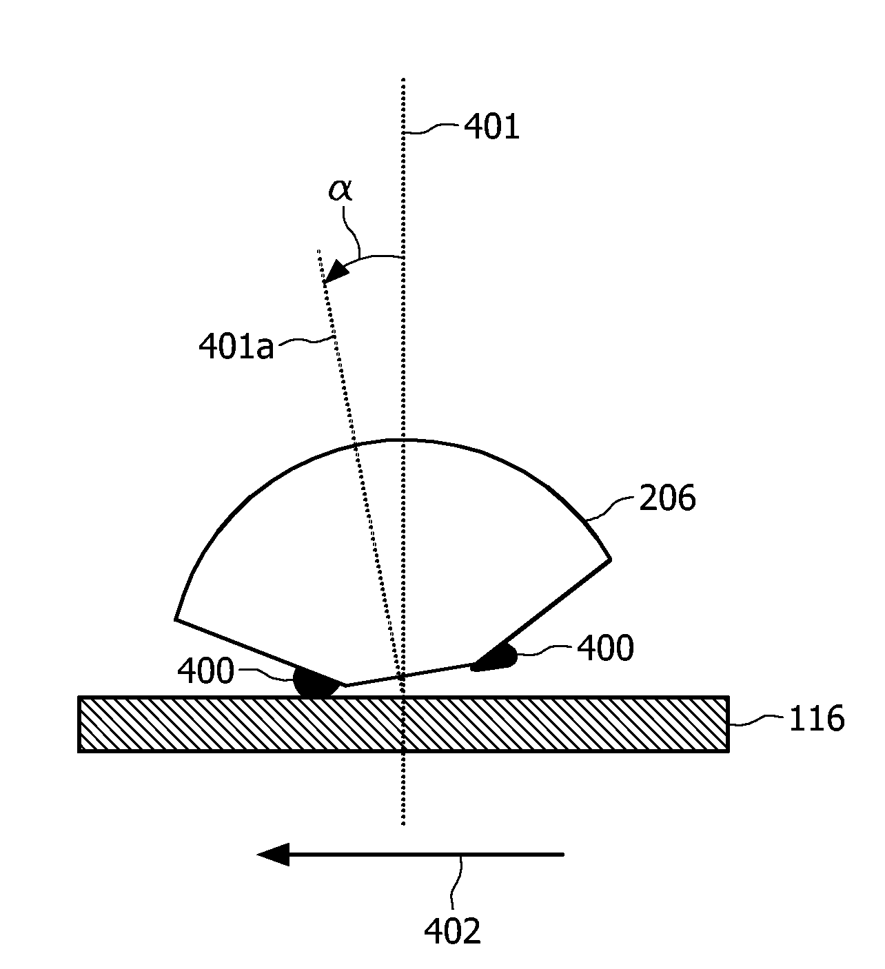
[0033]FIG. 4 illustrates a method of cleaning an optical exit surface (302,303) of a refractive element, in particular the SIL lens 206, according to the invention. While scanning an optical disc 115, the very small distance in the order of 20-50 nm between the optical disc 115 and the SIL lens 206 can lead to contamination of the SIL lens 206. This can be due to contamination present on the optical disc 115, residue from small contact / impact events, etc. Although said contamination may not give rise to immediate problems, a large amount of residue increases the chance of contamination or damage to the optical exit surface (302,303) of the SIL lens 206 and, should therefore be avoided. As mentioned, we observed that contamination mainly collects around the edge of the optical exit surface (302,303) of the SIL lens 206. Such contaminant accumulation at the edges of the optical exit surface (302,303) is illustrated in FIG. 4 by means of contamination material 400. Consequently, attemp...

second embodiment

[0041]FIG. 5 illustrates a method of cleaning an optical exit surface (302,303) of a SIL lens 206 according to the invention. Accordingly, a cleaning sequence of corresponding rotation and cleaning steps are performed.

[0042]In FIG. 5a and b, a top view of the optical exit surface (302,303) of a SIL lens 206 and of the cleaning pad 116 are shown. Arrow 503 indicates the possible rotation directions of the SIL lens 206; arrows 505a and 505b indicate the possible movement directions of the cleaning pad 116. Numerals 501 and 501 indicate two edges of the optical exit surface (302,303) of a SIL lens 206 that are being cleaned according to the method. In a first sequence of steps, as illustrated in the top view of FIG. 5b, the SIL lens 206 is rotated in a direction 506 so that edge 511 is a contact edge and edge 512 does not contact the cleaning pad 116. In the first cleaning step, the cleaning pad 116 is moved accordingly, as indicated by arrow 507. In a second sequence of steps, as illu...

third embodiment

[0047]FIG. 6 illustrates a method of cleaning a refractive element according to the invention;

[0048]The concepts as described hereinabove can be extended to cleaning the entire edge of optical exit surface (302,303) of the SIL lens 206, instead of only the (most important) leading and trailing edges. Preferably this is obtained by making use of a 4D actuator, allowing rotating of the SIL lens 206 in two perpendicular directions. FIG. 6 shows from a top view the circular edge of optical exit surface (302,303) of the SIL lens 206. The arrows 606 and 607 indicate the rotation direction available for rotation the SIL lens 206. The dashed axes indicate the possible movement directions of the cleaning pad 116 (for clarity, the cleaning pad 116 is not shown in FIG. 6). For example, in a cleaning method according to a third embodiment of the invention, the method starts by rotating the SIL lens 206 such that the edge of optical exit surface (302,303) is touching the cleaning pad 116 in poin...


PUM

PropertyMeasurementUnit
Angleaaaaaaaaaa
Angleaaaaaaaaaa
Areaaaaaaaaaaa

Abstract

A method of cleaning an optical exit face of refractive element of a near field optical scanning apparatus for scanning an optical disc, the method comprising a contacting step, comprising bringing into mechanical contact the refractive element and a cleaning pad such that the optical exit face of the refractive element is non-parallel to a surface of the cleaning pad, the refractive element contacting the surface pad along a contact edge and a first cleaning step, comprising at least a relative movement of the cleaning pad relative to the refractive element at least along cleaning axis, wherein the cleaning axis is in the plane of the surface of the cleaning pad and substantially perpendicular to the contact edge. The invention also related to a near field optical scanning apparatus enabled to clean a refractive element according to the said method.

Description

FIELD OF THE INVENTION[0001]The present invention relates generally to a method cleaning a refractive element of an optical scanning apparatus of the near field type. The present invention also relates to an optical scanning apparatus of the near field type.BACKGROUND OF THE INVENTION[0002]An optical scanning apparatus scans an optical disc by means of a radiation beam focused in a small spot onto the optical disc. By scanning an optical disc it is meant reading from and / or writing on an information layer in or on an optical disc. The maximum data density that can be read and / or recorded on an optical disc inversely scales with the size of the radiation spot that is focused onto the optical disc. The smaller the spot focused onto the disc, the larger the data density that can be recorded on the optical disc. The afore-mentioned spot size in turn is determined by the ratio of the wavelength λ of the scanning optical beam generated by the optical radiation source, for example a laser,...

Claims


Application Information

Patent Timeline
IPC IPC(8): G11B3/58C03C23/00G11B7/12G11B7/135
CPCG11B7/1201G11B2007/13727G11B7/1387G11B7/121
Inventor VERSCHUREN, COEN ADRIANUS
Owner KONINKLIJKE PHILIPS ELECTRONICS NV
Why Eureka
Try Eureka