Congestion control system, congestion control method, congestion control program, and program recording medium

a congestion control and program technology, applied in the field of congestion control system, congestion control method, congestion control program, and program recording medium, can solve the problems of soft switch itself stoppage, telephone communication function stoppage, etc., to prevent the occurrence of congestion in respective nodes and eliminate the effect of congestion

Inactive Publication Date: 2008-09-04
NEC CORP
View PDF5 Cites 27 Cited by
  • Summary
  • Abstract
  • Description
  • Claims
  • Application Information

AI Technical Summary

Benefits of technology

[0034]The present invention has been devised in view of the circumstances described above and it is an object of the present invention to provide a congestion control system, a congestion control method, a congestion control program, and a program recording medium that make it possible to prevent occurrence of congestion in respective nodes and eliminate occurring congestion by providing a congestion control server for controlling congestion in the respective nodes in a service network (e.g., a VoIP network in the case of a VoIP service) on an IP network for providing various communication services such as a VoIP service and a TVIP service.

Problems solved by technology

However, in the IP telephone service network (a telephone service network on the IP network), when a large number of calls to a specific incoming destination concentrate in the same period or when a large number of calls are originated from a specific outgoing source in the same period, it is likely that a large number of calls concentrate in a specific CTI-GW, congestion occurs, and a telephone communication function stops.
When a large number of calls concentrate in the soft switch, it is likely that the soft switch itself stops.
Besides, it is likely that functions of the entire IP telephone service stop.
For example, when control messages (call setting requests) are concentratedly originated from plural areas to a specific subscriber at a time, congestion occurs in a node that accommodates a user terminal of the subscriber.
When congestion occurs in a certain node configuring the IP telephone service network, it is highly likely that the congestion sequentially propagates to adjacent nodes connected to the node to make the entire network unstable.
However, in the service network on the IP network in the past that provides a communication service such as the VoIP service, as shown in FIG. 1, various problems related to traffic on the communication service such as the VoIP service occur.
A first problem is that, when VoIP outgoing calls from plural user terminals 80 (80-1, 80-2, etc.) in a specific area are generated in a burst-like manner, it is highly likely that entire VoIP-C plane 10 for the VoIP service on the IP network falls into a congestion state.
This leads to congestion in the entire network of VoIP-C plane 10.
Such a congestion problem in an originating system is a significant problem in the service network on the IP network that provides the VoIP service.
Therefore, relay node CL412-2 also causes congestion.
Therefore, subscriber accommodation node CL511-2 also causes congestion.
Furthermore, there is another problem.
However, when all the control messages are destroyed at a time, even an in-speech call is forcibly disconnected.
This is undesirable because accounting is affected.
When subscriber accommodation node CL511 of the originating system once falls into a congestion state in this way, a significant problem occurs in that occurrence of a situation undesirable in terms of call control cannot be prevented and congestion propagates to the entire VoIP network, i.e., the entire network of VoIP-C plane 10.
A second problem is in that, because means for controlling traffic among nodes configuring VoIP-C plane 10 for the VoIP service is not provided, a situation in which a large amount of traffic concentrates in specific relay node CL412 or the like cannot be prevented and it is highly likely that a congestion state of entire VoIP-C plane 10 is caused.
When relay node CL412 in VoIP-C plane 10 on the IP network congests, there is a significant problem in that congestion propagates to other nodes connected to relay node CL412 and the entire network of VoIP-C plane 10 falls into a congestion state and becomes unstable.
A third problem is that, since regulating means for regulating input traffic from PSTN 50 and other networks is not provided for control of network-to-network connection calls, it is highly likely that traffic concentrates in specific relay node CL412 or the like to cause a congestion state of entire VoIP-C plane 10.
Moreover, since means for solving a problem of collision of outgoing calls in network-to-network connection is not provided either, it is likely that not only a call setting operation for network-to-network connection calls is hindered but also congestion is caused by repeating exchange of processing requests between networks.
Since the other networks other than the VoIP network such as PSTN 50 cannot grasp a congestion situation of the VoIP network, it is likely that burst-like inflow of traffic into the VoIP network from the other networks occurs.
When burst-like inflow of traffic concerning a call setting request (a VoIP outgoing call) from the other networks such as PSTN 50 occurs, appropriate regulation control cannot be realized only by traffic regulation only in VoIP-C plane on the IP network and it is likely that the entire network of VoIP-C plane falls into a congestion state.
A fourth problem is that, since means for automatically regulating input traffic coming in a specific area is not provided, it is highly likely that traffic concentrates in specific subscriber accommodation node CL511 or the like on an incoming side to cause a congestion state of entire VoIP-C plane 10.
However, it is likely that the maintenance person omits inputting the maintenance command for input regulation or inputs a wrong command and occurrence of congestion cannot be prevented.
However, it is also likely that the maintenance person omits inputting such maintenance command for releasing the input regulation or inputs a wrong command and omission of release of the input regulation occurs.
Therefore, the technique is a congestion control method that spoils fairness with respect to the contracted number of calls of the subscriber and the number of generated calls in the past.

Method used


Image

  • Congestion control system, congestion control method, congestion control program, and program recording medium
  • Congestion control system, congestion control method, congestion control program, and program recording medium
  • Congestion control system, congestion control method, congestion control program, and program recording medium

Examples


first embodiment

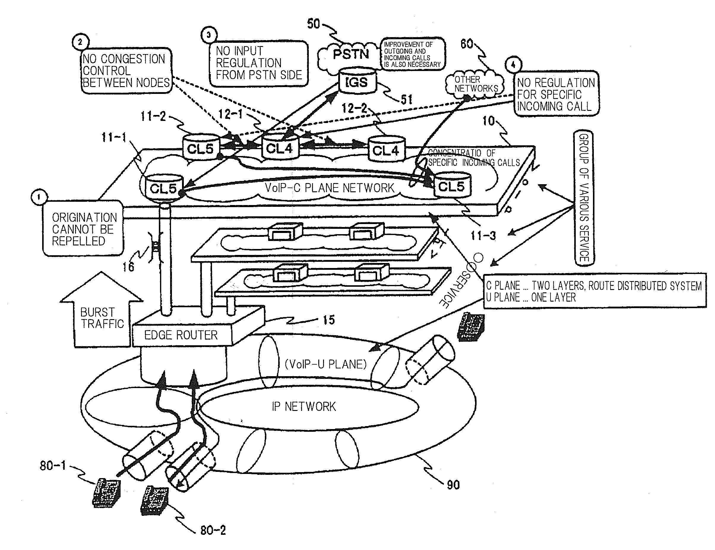
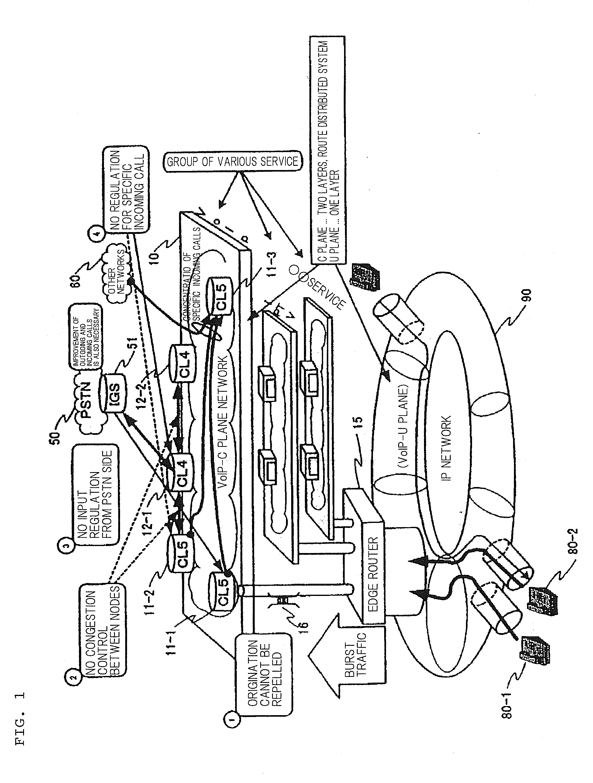
[0090]In the embodiment described above, an example of an operation for regulating transmission of a control message to subscriber accommodation node CL511 of the originating system that has fallen into a light congestion state or a heavy congestion state is explained with reference to FIG. 4.

[0091]FIG. 4 is a diagram for explaining operations in a first embodiment of congestion control system 100 according to the present invention. Specifically, FIG. 4 is a diagram for explaining an example of an operation for regulating, when it is detected that subscriber accommodation node CL511 is in a congestion sign state or has fallen into a congestion state, registration of a control message for call setting request concerning a new outgoing call among control messages to be registered in reception queue 16 of subscriber accommodation node CL511 from edge router 15 and suppressing a new originating call of user terminal 80.

[0092]In the VoIP network in the past, as described above, the mecha...

second embodiment

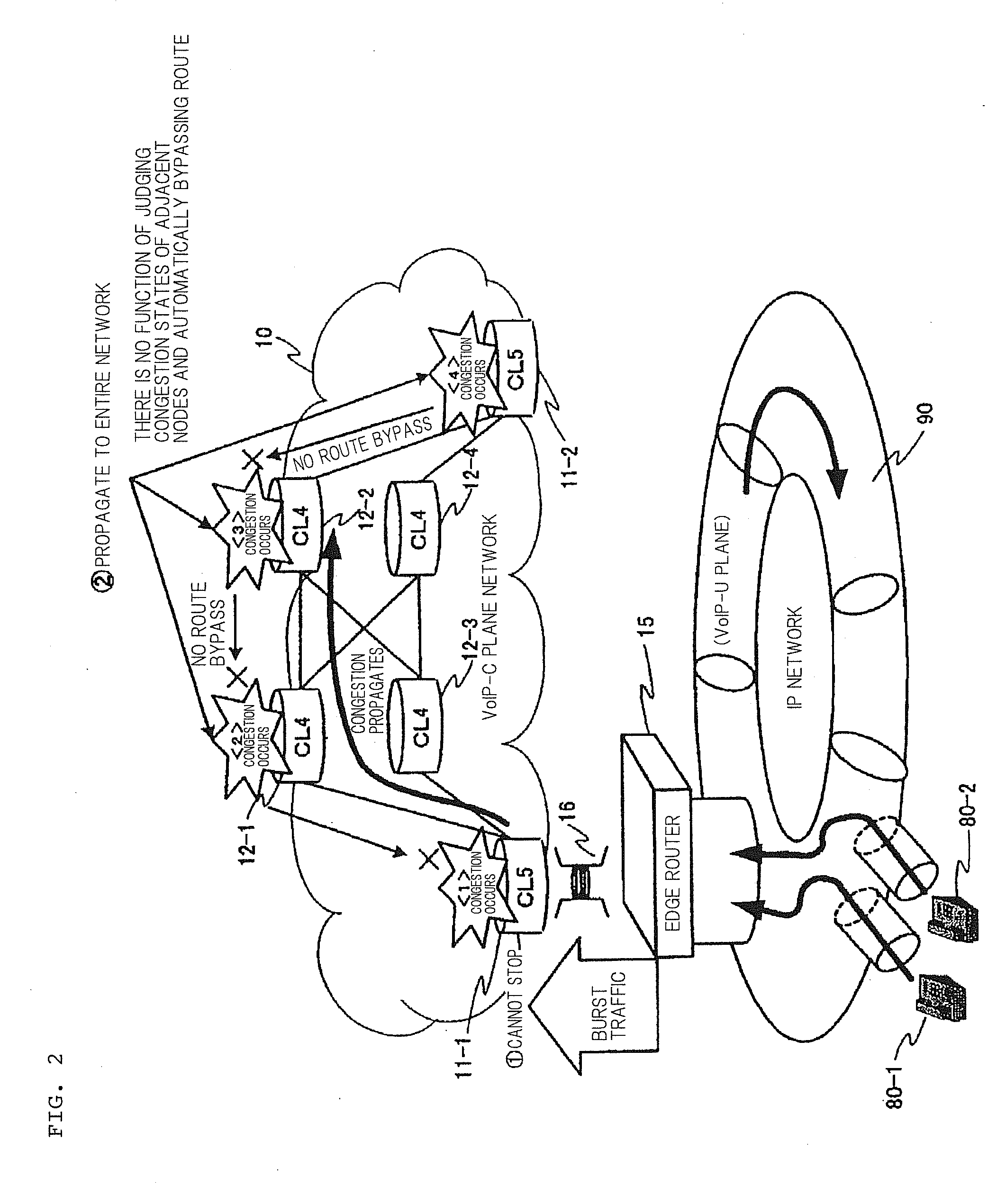
[0104]An example of an operation for bypassing a route of a control message to relay node CL412 that has fallen into a light congestion state or a heavy congestion state is explained with reference to FIG. 5.

[0105]FIG. 5 is a diagram for explaining an operation of a second embodiment of congestion control system 100 according to the present invention. In FIG. 5, for example, when it is detected that relay node CL412-1 shown in FIG. 3 is in a congestion sign state or has fallen in a congestion state, an operation for suppressing further generation of a load on relay node CL412-1 by bypassing a control message to relay node CL412-1 to another relay node CL412-2 is performed. This operation is explained with a case in which an SIP (Session Initiation Protocol) is adopted as a protocol for call control of a VoIP network as an example.

[0106]In the VoIP network in the past, a control message for processing request is fixedly routed and transmitted to a node in a specific route decided in ...

third embodiment

[0114]An example of an operation for regulating input of a control message from PSTN network 50 connected to relay node CL412 that has fallen into a light congestion state or a heavy congestion state is explained with reference to FIG. 4.

[0115]FIGS. 6A and 6B are diagrams for explaining operations in a third embodiment of congestion control system 100 according to the present invention. Specifically, FIGS. 6A and 6B are diagrams for explaining an operation for regulating, when it is detected that relay node CL412 to which PSTN network 50 is connected is in a congestion sign state or has fallen into a congestion state, a control message from PSTN network 50 relay node CL412 with a case in which an SIP (Session Initiation Protocol) is adopted as a protocol for call control for a VoIP network as an example.

[0116]In the VoIP network in the past, usually, when PSTN network 50 and VoIP network 10 are connected, as shown in FIG. 6A, STP (Signal Transfer Point) 52 on PSTN network 50 side an...


PUM


Abstract

In the present invention, a service network includes, when user terminals are divided by area, subscriber accommodation nodes that accommodate the user terminals present in the respective areas and relay nodes that perform relay of information among the subscriber accommodation nodes. The congestion control system further includes an edge router that routes a processing request for a communication service received from each of the user terminals to each of the subscriber accommodation nodes on the service network side as a control message and a congestion control server that controls congestion states of the subscriber accommodation nodes and the relay nodes. The subscriber accommodation node detects, when congestion occurs or it is likely that congestion occurs in the subscriber accommodation node because of a large number of control messages from the edge router, the occurrence of the congestion or the likelihood of occurrence of congestion and notifies the congestion control server to that effect. The congestion control server transmits a congestion control message for regulation to the edge router that routes the control message to the subscriber accommodation node, in which the congestion or the likelihood of occurrence of congestion has occurred, to thereby regulate an operation for routing the control message to the subscriber accommodation node, in which the congestion or the likelihood of occurrence of congestion has occurred, from the edge router.

Description

[0001]This application is based upon and claims the benefit of priority from Japanese patent application No. 2007-003595, filed on Jan. 11, 2007, the disclosure of which is incorporated herein in its entirety by reference.BACKGROUND OF THE INVENTION[0002]1. Field of the Invention[0003]The present invention relates to a congestion control system, a congestion control method, a congestion control program, and a program recording medium, and, more particularly to a congestion control system, a congestion control method, a congestion control program, and a program recording medium for controlling traffic (communication amount) in an IP telephone system for providing a telephone communication service (VoIP (Voice over Internet Protocol)) through an IP network.[0004]2. Description of the Related Art[0005]When the IP telephone service for performing telephone communication through the IP network is realized, a CTI (Computer Telephony Integration) technique for integrating functions of a co...

Claims


Application Information

Patent Timeline
Patent Type & Authority Applications(United States)
IPC IPC(8): G08C15/00H04L12/24H04L12/26H04L12/801H04L12/911
CPCH04L41/06H04L47/10H04L65/80H04L47/12H04L47/263H04L47/11
Inventor NAKAYMA, YOSHITAROUYOSHIZU, HIROTAKAINOUE, KAZUKI
Owner NEC CORP
Why Eureka
Try Eureka