Appliance for Converting Digital Audio Broadcast (Dab) Signals

Inactive Publication Date: 2008-09-04
KONINKLIJKE PHILIPS ELECTRONICS NV
View PDF2 Cites 16 Cited by
  • Summary
  • Abstract
  • Description
  • Claims
  • Application Information

AI Technical Summary

Benefits of technology

[0004]It is an object of the invention to remedy this situation and to provide an appliance of the type specified above that enables the consumer to retain existing audio systems, including those with FM tuners, even if a switch from conventional FM radio systems to the new DAB system is undertaken.
[0006]In accordance with a further object of the invention, the appliance is to be of a simple, economical design and, in particular, to be easy to operate for the first-time setting, wherein any subsequent operation will preferably be unnecessary in the normal case.
[0010]With the present appliance, also referred to below as a DAB / FM converter, a desired channel set by a user at the FM receiver is identified on the basis of the local oscillator frequency (which is known to differ by 10.7 MHz—the intermediate frequency—from the transmission frequency) generated in the FM receiver in accordance with the set reception frequency. An identification or detection of the local oscillator frequency in this manner via the wired connection means on the basis of the leakage signals (residues) transmitted via these wired connection means is readily possible. The frequency detection means used hereby may be designed in a manner that is conventional per se. A comparatively complex embodiment for this is described in, for example, document U.S. Pat. No. 4,723,302 A, wherein the aim is to establish which FM channel an FM receiver is currently receiving. The frequency detection means are, however, preferably realized with the aid of an auxiliary FM receiver, which is known per se, for example using a single-chip tuner module available on the market, designated TEA 5777, from Philips Semiconductors. This auxiliary FM receiver has a rapid transmitter scanning function and can in this way find the local oscillator frequency rapidly and can lock onto it using a phase-locked loop (PLL circuit). The reception frequency range can be adjusted for a frequency band in the range from 98.20 MHz to 118.70 MHz (if, in accordance with the given standard, the local oscillator frequency lies at the value of the intermediate frequency of 10.7 MHz above the transmission frequency, wherein the transmission frequency lies in the FM band between 87.50 MHz and 108.00 MHz worldwide) or for a frequency band in the range from 63.30 MHz to 79.30 MHz (in the case of the Japanese standard, where the local oscillator frequency lies at the value of the intermediate frequency of 10.7 MHz below the transmission frequency).

Problems solved by technology

As a result, this known appliance is complicated to operate; it is also disadvantageous to the extent that a carrier frequency that has been found and selected will not necessarily remain free pending the tuning of the appliance, i.e. the FM modulator means in the appliance, so it is often necessary to look for another free frequency.
The known appliance is intended, in particular, for applications in motor vehicles, and its application in stationary domestic systems, i.e. hi-fi stereo systems and the like, which are frequently costly, would appear to make little sense, owing to the alternative options that are available for these systems.
However, this would mean that, following the introduction of this DAB system, a large number of conventional FM receivers would suddenly become useless, since FM radio signals would no longer be transmitted, and the existing FM receivers would be replaced with DAB appliances.
Quite apart from the enormous environmental pollution caused by the disposal of the existing FM receivers, high costs for consumers would be involved as a result of the procurement of the new DAB appliances, which is all the more significant when the static domestic audio systems, which are costly per se, are taken into account.

Method used


Image

  • Appliance for Converting Digital Audio Broadcast (Dab) Signals
  • Appliance for Converting Digital Audio Broadcast (Dab) Signals
  • Appliance for Converting Digital Audio Broadcast (Dab) Signals

Examples


Embodiment Construction

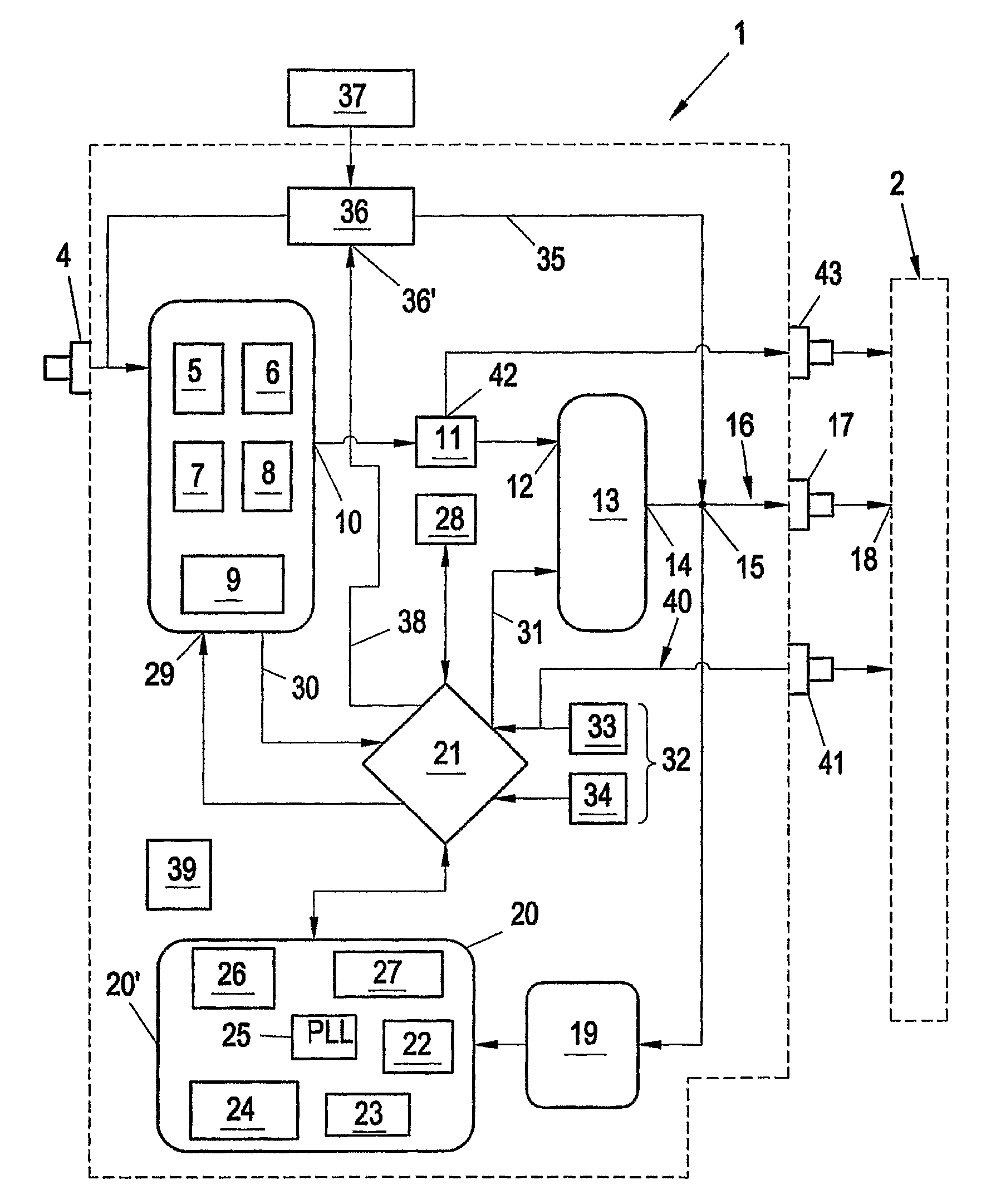
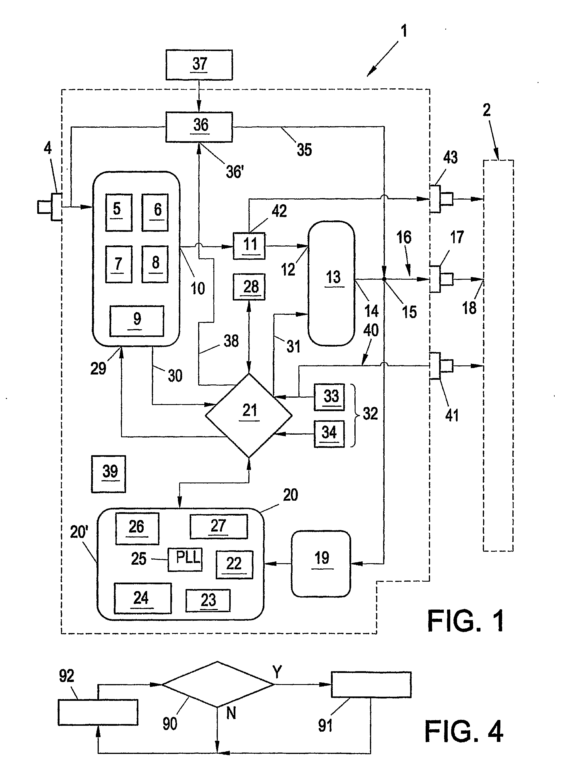
[0025]FIG. 1 shows, schematically, an appliance 1 for converting DAB signals into FM signals and for transmitting these FM signals to an FM receiver 2. In accordance with FIG. 1, the appliance 1 is equipped with DAB reception means 3 that are conventional per se, and are connected to an antenna (not shown) via an antenna input jack 4. As usual per se, the DAB reception means 3 are equipped with an input stage 5 and with an FFT, demultiplexer and channel-decoder module 6 (FFT=Fast Fourier Transformation) and with a deinterleaver, FIC-decoder and PAD-decoder module 7 (FIC=Fast Information Channel, PAD=Program Associated Data) and with an audio decoder 8 and with a serial interface 9. At an output 10, the DAB reception means 3 contained in the appliance 1 emit a digital audio signal, which digital audio signal is supplied to a D / A converter 11 for the purpose of generating an analog audio signal. The appliance 1 is further equipped with FM modulator means 13, which FM modulator means 1...


PUM


Abstract

The invention relates to an appliance (1) for converting DAB signals into FM signals and for transmitting the FM signals to an FM receiver (2), with a DAB receiver (3), which is equipped with an antenna input (4) and, at an output (10), emits an audio signal derived from a received DAB signal, and with an FM modulator unit (13) for generating an FM signal modulated with the audio signal, and a transmission unit for transmitting the FM signal to the FM receiver (2), and with a control stage (21), wherein the transmission unit is equipped with wired connection means (16), to which wired connection means (16) frequency detection means (20) are connected, which are connected to the control means (21) and arranged to detect the high frequency set in the FM receiver (2), and to generate a result signal representing the detection result and deliver it to the control stage (21) for channel setting purposes, and wherein the control stage (21) is connected to a channel-setting input (29) of the DAB receiver (3) in order to tune the DAB receiver (3) on the basis of the result signal.

Description

FIELD OF THE INVENTION[0001]The invention relates to an appliance for converting DAB signals into FM signals and for transmitting the FM signals to an FM receiver with DAB reception means, which DAB reception means are equipped with an antenna input and, at an output, emit an audio signal derived from a received DAB signal, and with FM modulator means for generating an FM signal modulated with the audio signal, and with transmission means for transmitting the FM signal to the FM receiver, and with control means.BACKGROUND OF THE INVENTION[0002]An appliance of this kind is known from document U.S. Pat. No. 6,493,546 B2. With this known appliance, what is involved is the conversion of an audio signal originating from an auxiliary source into the FM (Frequency Modulation) band, and sending it via a wireless link or transmission to a radio device, i.e. an FM receiver. Serving as the auxiliary source may be, for example, a satellite broadcast receiver, in particular a DAB (Digital Audio ...

Claims


Application Information

Patent Timeline
IPC IPC(8): H04H20/47H04B1/38H04B1/50H04H20/72
CPCH04H20/08H04H2201/20H04H40/00H04H20/72
Inventor ULLMANN, PAUL
Owner KONINKLIJKE PHILIPS ELECTRONICS NV
Why Eureka
Try Eureka