Wind Turbine Pitch Bearing, and Use Hereof

a technology of wind turbines and bearing rings, applied in the field of wind turbines, can solve the problems of large balls, increased bearing cost and weight, and economic disadvantage, and achieve the effect of facilitating the adjustment of bearing rings and handling distortion and misalignmen

Active Publication Date: 2008-09-04
VESTAS WIND SYST AS
View PDF17 Cites 48 Cited by
  • Summary
  • Abstract
  • Description
  • Claims
  • Application Information

AI Technical Summary

Benefits of technology

[0065]By making the rollers bulges at the middle, they are able to handle distortion and misalignment of the bearing rings more efficiently.

Problems solved by technology

To ensure this the obvious solution would be simply to make the pitch bearings bigger, but the bearing balls has already almost reached the limit of what is industrially available, and bigger balls would therefore be economically disadvantageous.
Furthermore, the ring size would increase with increased ball size and thereby increase the bearing cost and weight significantly.
But this design is space consuming and requires a high degree of rigidity and thereby increased cost and weight of both the hub and the blades.

Method used


Image

  • Wind Turbine Pitch Bearing, and Use Hereof
  • Wind Turbine Pitch Bearing, and Use Hereof
  • Wind Turbine Pitch Bearing, and Use Hereof

Examples


Embodiment Construction

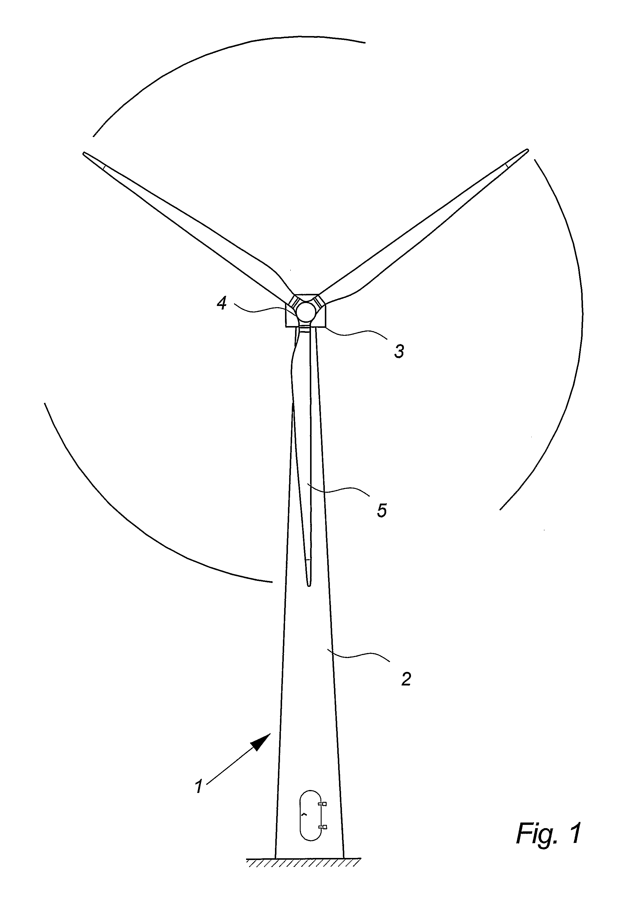
[0087]FIG. 1 illustrates a wind turbine 1, comprising a tower 2 and a wind turbine nacelle 3 positioned on top of the tower 2. The wind turbine rotor 4, comprising two wind turbine blades 5, is connected to the nacelle 3 through the low speed shaft which extends out of the nacelle 3 front.

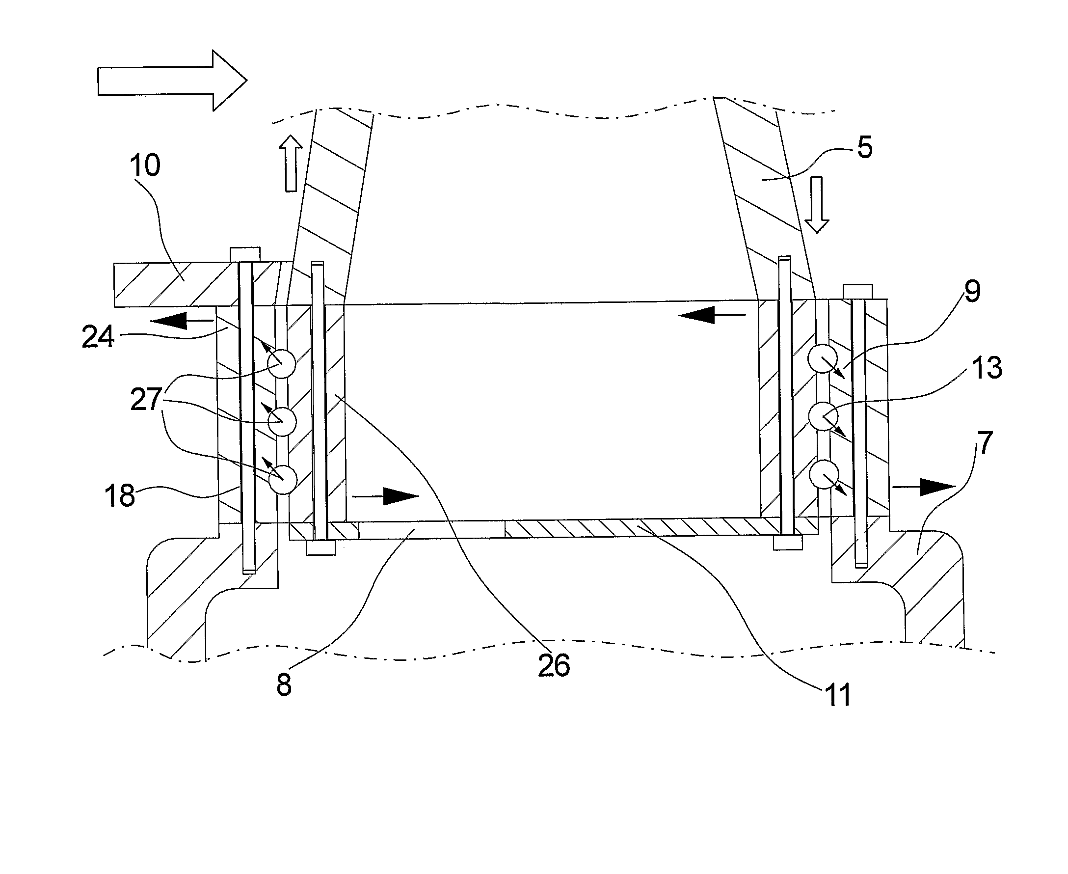
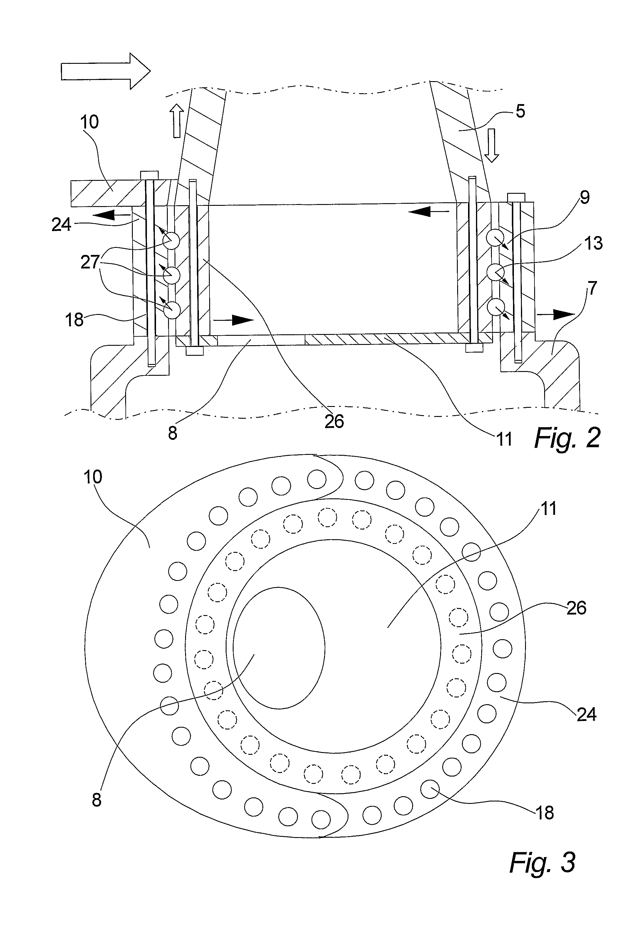
[0088]FIG. 2 illustrates a cross section of a wind turbine blade 5 connected to a hub 7 through an embodiment of a pitch bearing 9. In this embodiment the pitch bearing 9 is a triple row 27 ball bearing, but it could also be a double or four rowed 27 bearing.

[0089]The pitch bearing has to transfer forces mainly from three different sources. The blade 5 (and the bearings 9 themselves off cause) is under constant influence of the force of gravitation. The direction of the gravitational force varies depending on the blades 5 position, inducing different loads on the pitch bearings 9. When the blade is in motion the bearing 9 is also under influence of a centrifugal force, which mainly produces an axia...


PUM


Abstract

The invention relates to a wind turbine including at least two pitch controlled wind turbine blades. Each blade has pitch bearings including two or more bearing rings, and pitch controlling means for pitching the blades by means of the bearings. The blades are mounted on a hubs via the pitch bearings and the pitch bearings include separate flexibility enhancing means for controlling loads in the bearings.

Description

TECHNICAL FIELD OF THE INVENTION[0001]The invention relates to a wind turbine and use hereof.DESCRIPTION OF THE RELATED ART[0002]A wind turbine known in the art comprises a wind turbine tower and a wind turbine nacelle positioned on top of the tower. A wind turbine rotor with three wind turbine blades is connected to the nacelle through a low speed shaft, which extends out of the nacelle front as illustrated on FIG. 1.[0003]Modern wind turbines control the load on the rotor by pitching the blades in and out of the incoming wind. The blades are pitched to optimize the output or to protect the wind turbine from damaging overloads.[0004]To perform the pitch each blade is provided with a pitch bearing between the hub and the blade, and some sort of mechanism, most often a hydraulic cylinder, to provide the force for pitching the blade and maintaining it in a given position. This pitching arrangement enables each blade to be turned approximately 90° around their longitudinal axis.[0005]T...

Claims


Application Information

Patent Timeline
Patent Type & Authority Applications(United States)
IPC IPC(8): F03D11/00F16C19/00
CPCF03D1/0658F16C41/02F03D11/0008F05B2260/79F16C19/18F16C19/38F16C23/08F16C27/04F16C33/3818F16C33/60F16C2300/14Y02E10/721Y02E10/722Y02E10/723F03D7/0224F16C19/381F03D80/70F16C2360/31F16C19/08Y02E10/72
Inventor BECH, ANTONMADDEN, GERRY
Owner VESTAS WIND SYST AS
Why Eureka
Try Eureka