Ball-and-Socket Joint and Universal Shaft

a ball-and-socket joint, universal shaft technology, applied in the direction of couplings, yielding couplings, couplings, etc., can solve the problems of increasing assembly time, unsuitable elastic materials of sealing boots for transmitting high torque transmission, and soft elastic materials of sealing boots. , to achieve the effect of effective damping oscillations and vibrations, high torque and small installation space requirements

Inactive Publication Date: 2008-09-04
SHAFT FORM ENG GMBH
View PDF9 Cites 7 Cited by
  • Summary
  • Abstract
  • Description
  • Claims
  • Application Information

AI Technical Summary

Benefits of technology

[0005]It is therefore an object of the present invention to provide a ball joint and a drive shaft of the aforementioned type for transmitting a high torque, which effectively dampens oscillations and vibrations with a small installation space requirement.

Problems solved by technology

In addition, the time taken up by assembly work increases, due to the additional damping element to be inserted.
Assembling this rotary ball joint is particularly labor intensive, since the joint must be inserted into the sealing boot.
In addition, the soft, elastic material of the sealing boot is unsuited to transmitting high torque transmission.

Method used


Image

  • Ball-and-Socket Joint and Universal Shaft
  • Ball-and-Socket Joint and Universal Shaft
  • Ball-and-Socket Joint and Universal Shaft

Examples


Embodiment Construction

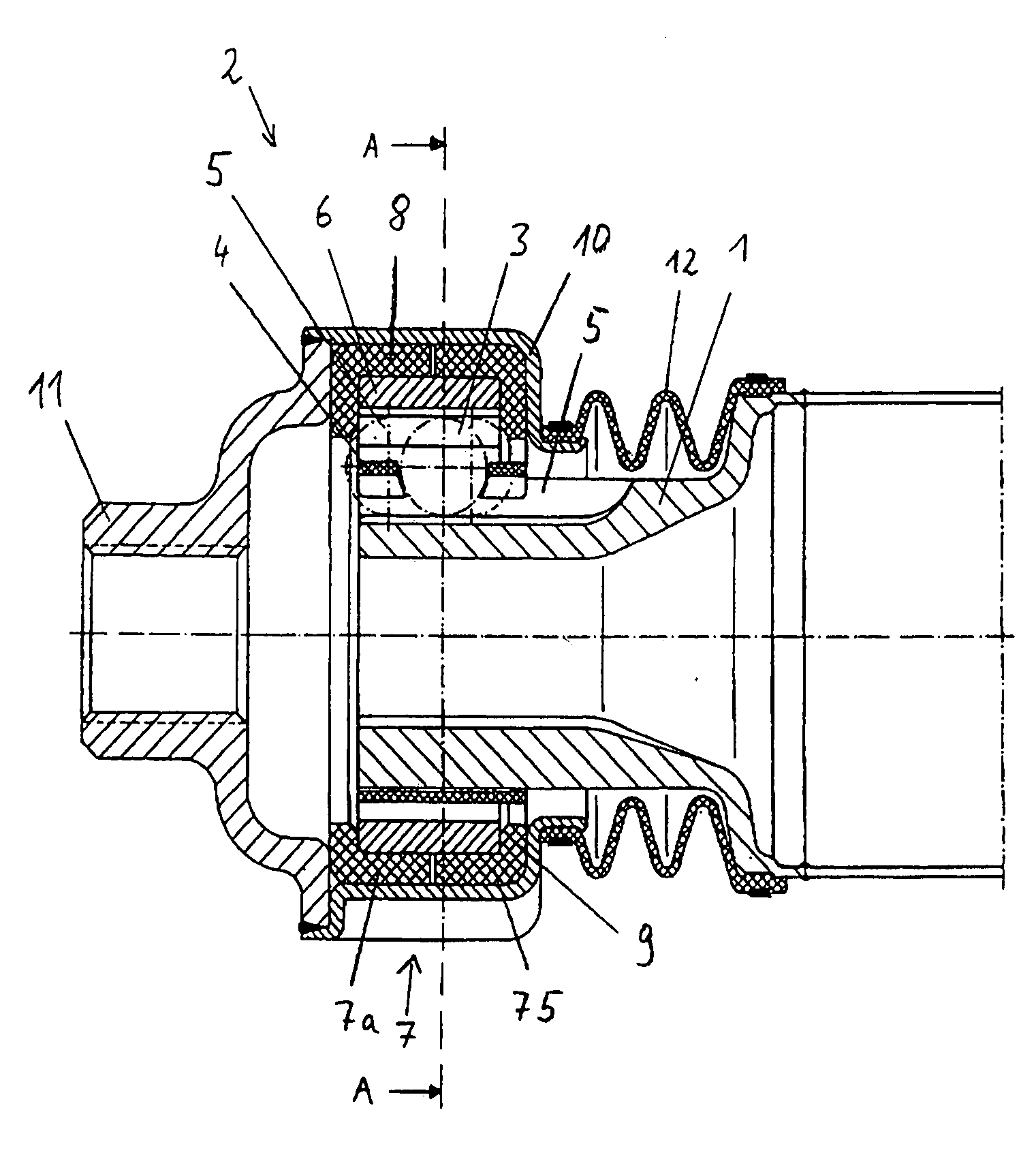
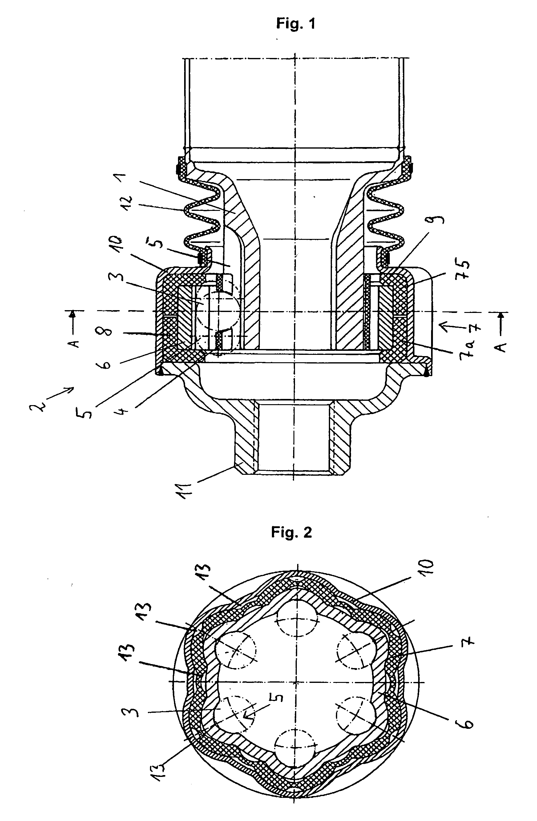
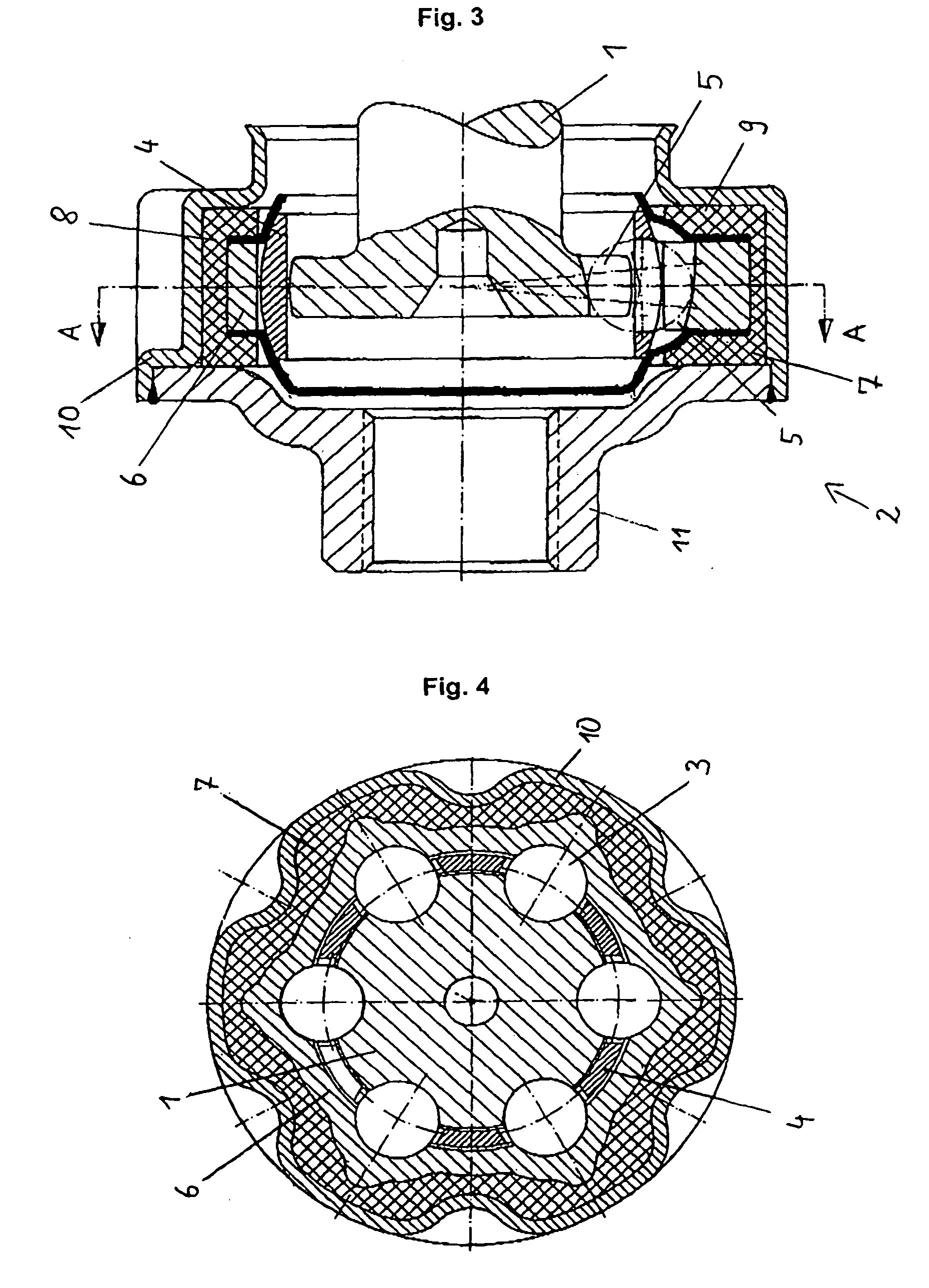
[0021]The ball joints shown in the drawing figures each comprise an inner hub 1 (not shown in FIG. 2), an outer hub 2 and a ball 3, which are arranged in a cage 4 between the inner hub 1 and the outer hub 2. For this purpose associated pairs of aligned tracks 5 are provided in which the balls 3 are accommodated.

[0022]The joint shown in FIGS. 1 and 2 is constructed as a slip joint, in which the tracks 5 extend in at least an approximately axial direction, so that the inner hub 1 can be moved a defined distance relative to the outer hub 2, whereby the balls 3 roll along the tracks 5. In contrast to this, the ball joints in FIGS. 3, 4 and 6 are shown as fixed joints constructed as counter track ball joints that essentially allow only an angular movement between the inner hub 1 and the outer hub 2.

[0023]The outer hub 2 in the joints shown in FIGS. 1 to 4 is comprised of an at least approximately ring-shaped inner element 6, on the inner surface of which the tracks 5 are provided. The in...


PUM


Abstract

A ball-and-socket joint comprising an inner hub (1) and an outer hub (6) inside which tracks are disposed that are associated with each other in pairs. At least one ball is arranged in each track in order to transmit torque between the inner hub and the outer hub. The ball-and-socket joint further includes at least one diaphragm which seals the outer hub with respect to a joining element that can be connected in a torsion-proof manner to the inner hub. The outer hub is provided with a metallic interior element encompassing the tracks, a dampening element which embraces the interior element in at least some areas, and a cap that embraces the damping element in at least some areas in order to connect the outer hub to a driving part or a part to be driven. The damping element is made of a material having a modulus of elasticity lower than the modulus of elasticity of the metallic material of the interior element and/or the cap of the outer hub while being greater than the modulus of elasticity of the diaphragm.

Description

CROSS REFERENCE TO RELATED APPLICATIONS[0001]This application is a continuation of international patent application no. PCT / EP2006 / 008297, filed Aug. 24, 2006, designating the United States of America and published in German on Mar. 22, 2007 as WO 2007 / 031181, the entire disclosure of which is incorporated herein by reference. Priority is claimed based on Federal Republic of Germany patent application no. DE 10 2005 043 840.7, filed Sep. 13, 2005.BACKGROUND OF THE INVENTION[0002]The invention relates to a ball joint, which can be used for torque transmission in the driveline of a car. Further, the present invention relates to a drive shaft with a ball joint of this type.[0003]U.S. Pat. No. 6,251,021 (=DE 198 31 015) discloses a drive configuration with a constant velocity fixed joint, the outer part of which has a flange extending outwards away from this part, it being possible to connect the flange to an annular damping element. The damping element is positioned between the flange ...

Claims


Application Information

Patent Timeline
Patent Type & Authority Applications(United States)
IPC IPC(8): F16D3/16F16D3/223F16D3/2237
CPCF16D3/2237F16D2300/22F16D2003/2232F16D2003/22316
Inventor JACOB, WERNERJACOB, MARTIN D.
Owner SHAFT FORM ENG GMBH
Why Eureka
Try Eureka