Splitable tip catheter with bioresorbable adhesive

a bioresorbable adhesive and tip catheter technology, applied in the field of multi-lumen catheters, can solve the problems of reducing blood flow rate, inadequate dialysis, reducing clearance, etc., and achieve the effects of facilitating distal tip insertion, facilitating distal end insertion, and facilitating separation

a bioresorbable adhesive and tip catheter technology, applied in the field of multi-lumen catheters, can solve the problems of reducing blood flow rate, inadequate dialysis, reducing clearance, etc., and achieve the effects of facilitating distal tip insertion, facilitating distal end insertion, and facilitating separation

US20080214980A1Active Publication Date: 2008-09-04BARD ACCESS SYST

Image

  • Splitable tip catheter with bioresorbable adhesive
  • Splitable tip catheter with bioresorbable adhesive
  • Splitable tip catheter with bioresorbable adhesive

Examples


Embodiment Construction

[0043]As used herein, the term “bioresorbable” refers to materials that are biodegradable or biosoluble such that they degrade or break down by mechanical degradation upon interaction with a physiological environment into components that are metabolizable or excretable over a period of time.

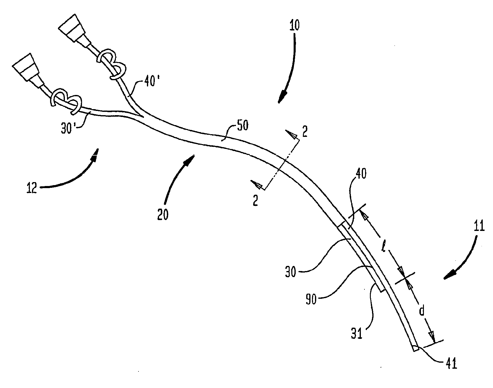
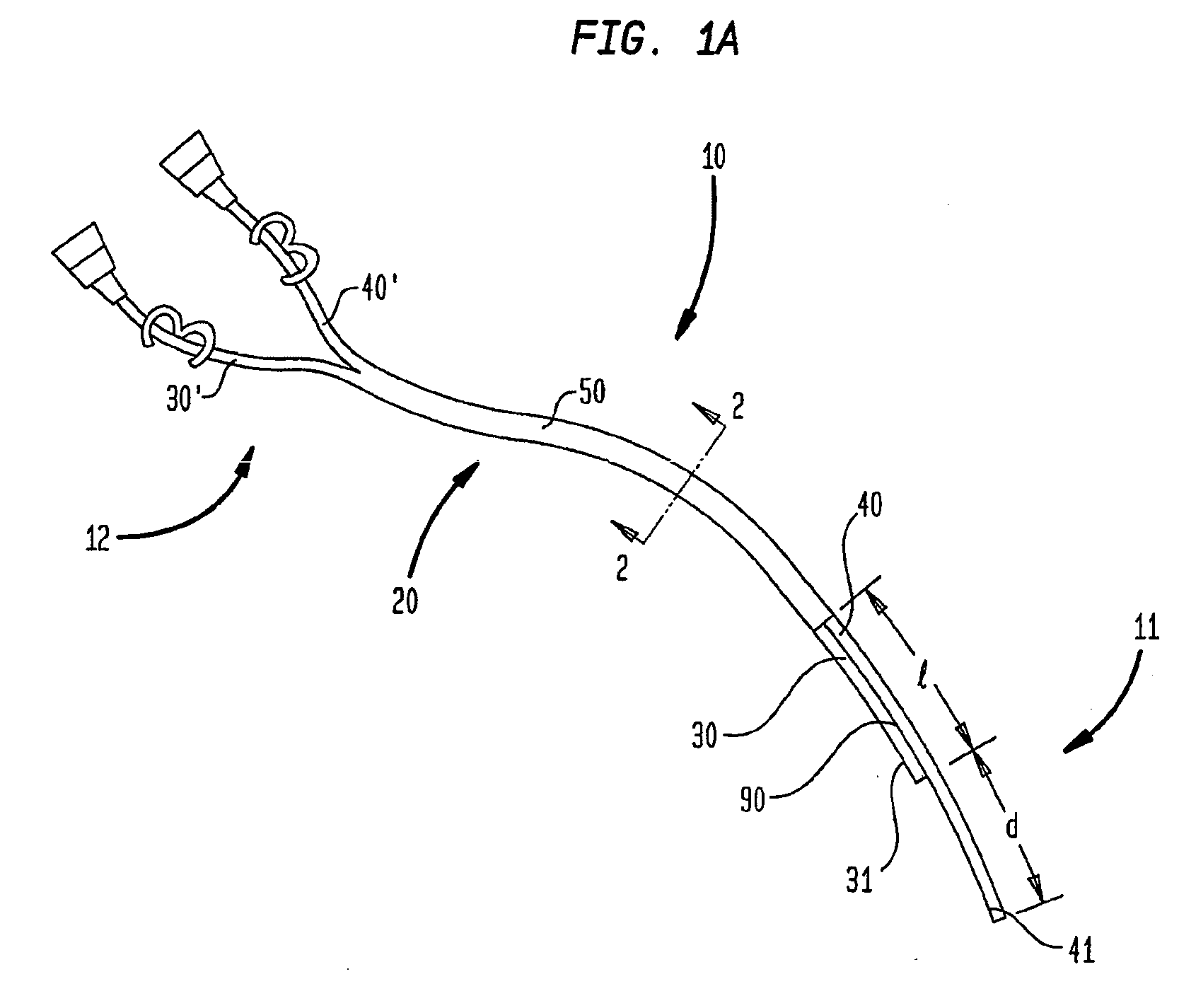
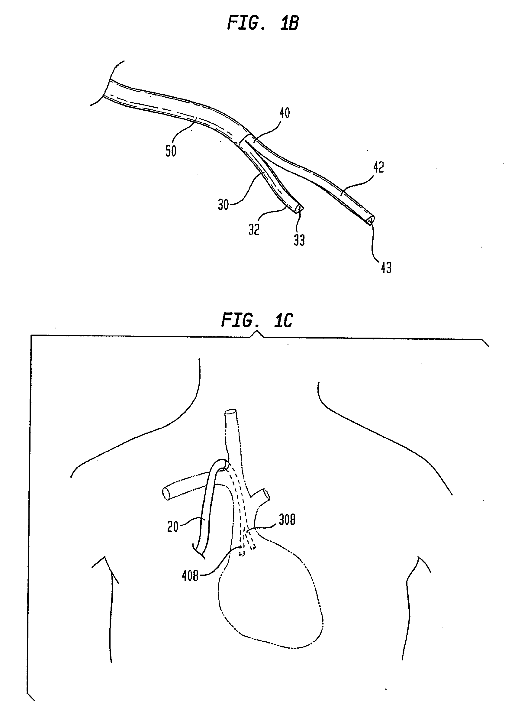
[0044]The present invention includes various embodiments of a multi-lumen catheter for hemodialysis and methods of use. As shown in FIGS. 1A and 1B, one embodiment of catheter 10 includes an elongate body 20 having proximal and distal end 11 and 12, and at least one blood extraction lumen 30 and at least one blood return lumen 40 extending longitudinally therethrough. Each lumen 30, 40 has a proximal end 30′, 40′ adapted to direct fluid to, or couple directly with, a hemodialysis apparatus (not shown), and a distal end 31, 41 for insertion into a blood vessel. Distal extraction and return tip portions 32, 42 of each lumen 30, 40 include a distal end opening 33, 43 formed therein to provide for si...


PUM


Abstract

Splitable-tip catheters are disclosed with bioresorbable adhesive to provide spatial separation of distal tip elements during use. The invention can be particularly useful in hemodialysis applications where it is desirable to separate blood extraction and return lumens. The adhesive facilitates insertion of the distal end of the catheter as an assembly, e.g., into a blood vessel using a single guidewire, while the bioresorbable nature of the adhesive allows the tip elements to separate in vivo.

Description

CROSS-REFERENCE TO RELATED APPLICATIONS[0001]This application is a divisional of U.S. patent application Ser. No. 10 / 874,298 filed on Jun. 9, 2004 and entitled “Splitable Tip Catheter With Bioresorbable Adhesive,” which is hereby incorporated by reference in its entirety.FIELD OF THE INVENTION[0002]The present invention generally relates to catheters and preferably to multi-lumen catheters used for vascular access.BACKGROUND OF THE INVENTION[0003]Multi-lumen catheters and, in particular split-tip catheters, are desirable for various treatment applications such as hemodialysis where fluid extraction and infusion occur simultaneously. Hemodialysis is the separation of metabolic waste products and water from the blood by diffusion through a semipermeable membrane. Typically, a hemodialysis unit is connected to a patient's body by a catheter. The catheter's distal end is placed in a blood vessel and its proximal end is connected to a hemodialysis unit.[0004]During hemodialysis, a patien...

Claims


Application Information

Patent Timeline
04 Sep 2008
Publication
US20080214980A1
IPC
A61M1/14; A61M25/00; A61M37/00
CPC
A61M25/0032; A61M25/0068; A61M25/007; A61M25/0074; A61M25/008; A61M25/003; A61M2025/0034; A61M25/0071
Inventors
ANAND, PJ