Supercharge Your Innovation With Domain-Expert AI Agents!

Fluorescent lamp and imaging device usign the same

a fluorescent lamp and imaging device technology, applied in the field of phosphor layer, can solve the problems of image quality and important reduction of variation, and achieve the effects of reducing variation in chromaticity, enhancing luminance, and increasing manufacturing cos

Inactive Publication Date: 2008-09-11
HITACHI DISPLAYS
View PDF14 Cites 2 Cited by
  • Summary
  • Abstract
  • Description
  • Claims
  • Application Information

AI Technical Summary

Benefits of technology

[0016]In recent years, liquid crystal display devices have been widely used mainly in the market of large-sized liquid crystal TV receivers, and lower cost and higher image quality have been demanded. In order to satisfy these demands, higher brightness and reduction in variation in chromaticity of a CCFL, a light source, should be achieved.
[0017]Especially, higher brightness of a CCFL is an important issue, and if the issue is solved, liquid crystal display devices can be produced at a lower cost. For example, when designing a back light unit having the same luminance as with a conventional unit, it becomes possible to reduce the number of CCFLs than that of the conventional one, and further considering that the number of converters can also be reduced at a time, a back light unit can be produced at a greatly lower cost. Furthermore, a CCFL with higher brightness can omit some of the optical members (for example, luminance improving film etc.) that intervene between the CCFL and a liquid crystal display panel, which enables a liquid crystal display device to be produced at a lower cost.

Problems solved by technology

On the other hand, variation in chromaticity of a CCFL is a factor which greatly affects the image quality of a liquid crystal display device, therefore reduction of the variation is an important issue.

Method used


Image

  • Fluorescent lamp and imaging device usign the same
  • Fluorescent lamp and imaging device usign the same
  • Fluorescent lamp and imaging device usign the same

Examples


first embodiment

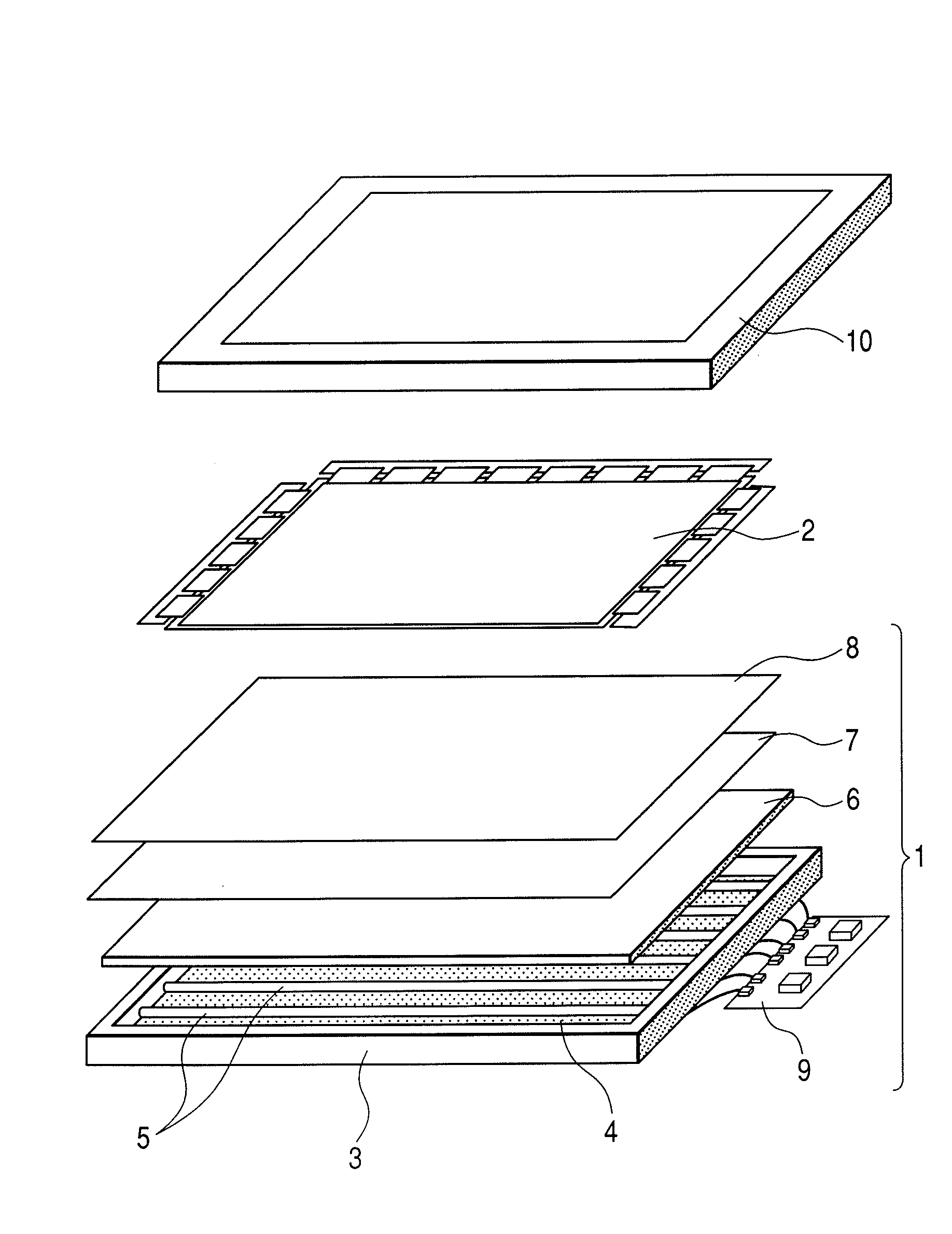
[0046]An imaging device having a structure according to an aspect of the present invention was produced by the following method, and the property thereof was evaluated. A liquid crystal display device in the present embodiments is composed of a back light unit 1 and a liquid crystal display panel 2, as shown in FIG. 4. The back light unit 1 includes a white light source 5, a drive circuit 9 (inverter) for lighting the light source, a frame 3, a reflector 4, a diffuser plate 6, a prism sheet 7, and a reflective polarizer 8. The above back light unit is an example; therefore, the unit need not include all of the component parts mentioned above, or may add another part. In short, a back light unit means what illuminates the liquid crystal display panel 2 in order to form images.

[0047]In the present embodiments, a CCFL shown in FIG. 5 was used as a white light source. At the time, a CCFL using a phosphor layer which was mixed with a red phosphor, green phosphor, and blue phosphor was pr...

second embodiment

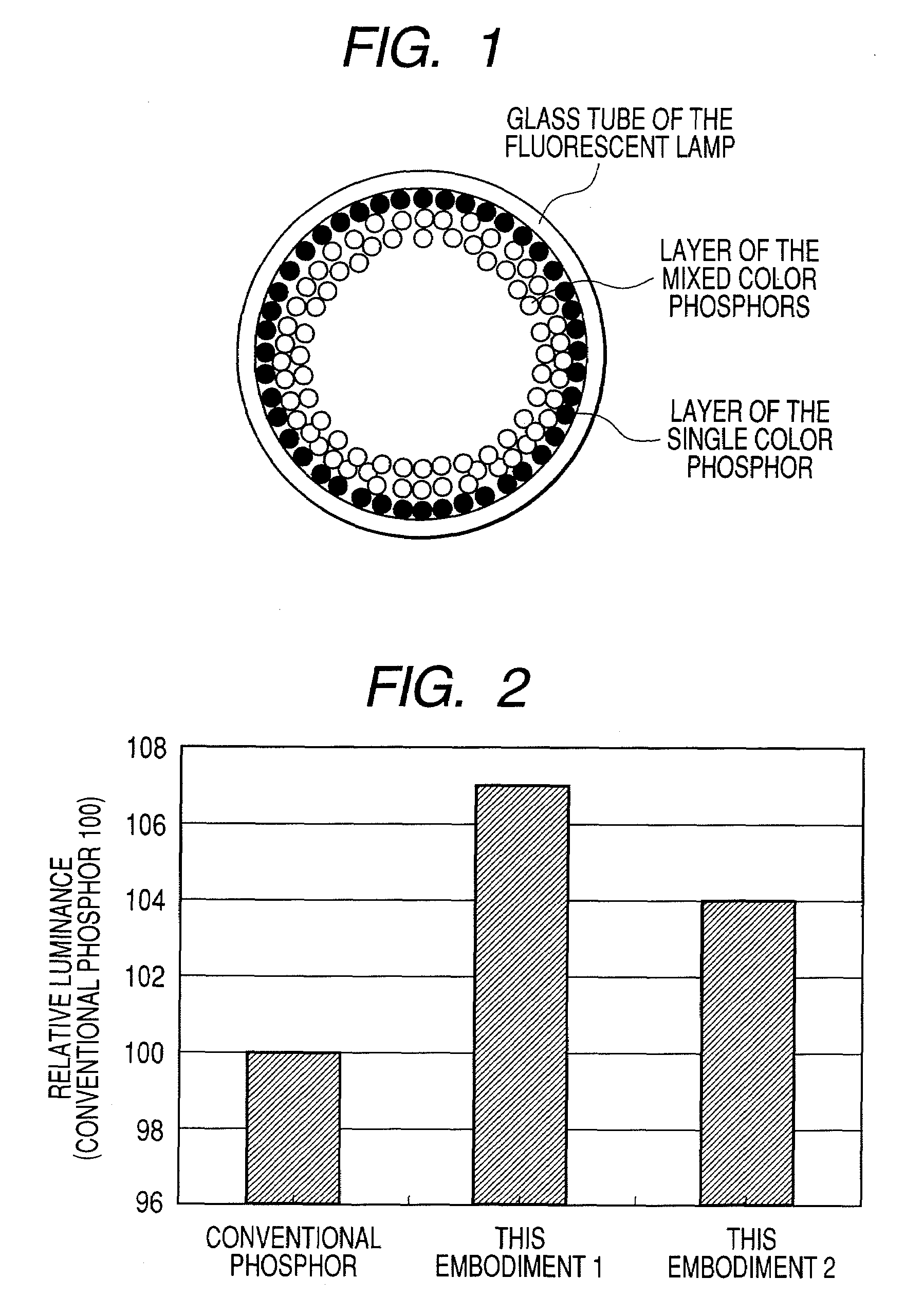
[0058]The second embodiment was produced in the same way as with the first embodiment. A difference between the second embodiment and the first embodiment is that in the second embodiment, two layers of phosphors were formed: one layer was formed by using a single suspension of a blue phosphor BaMgAl10O17:Eu2+; and the other layer by using a suspension mixed with three color phosphors.

[0059]Particles of these all phosphors used had diameters of which median diameters d50 were in the range of 1.0 μm to 10.0 μm. According to the second embodiment, a layer structure of the present invention, which is shown in FIG. 1, was produced. In this case, a layer of the single color phosphor of FIG. 1 is made of a blue phosphor.

[0060]White luminance was measured in the conventional phosphor and the second embodiment, and the result is shown in FIG. 2, in which values of the second embodiment show relative luminance against the values of the conventional phosphor which are 100. It can be understoo...

third embodiment

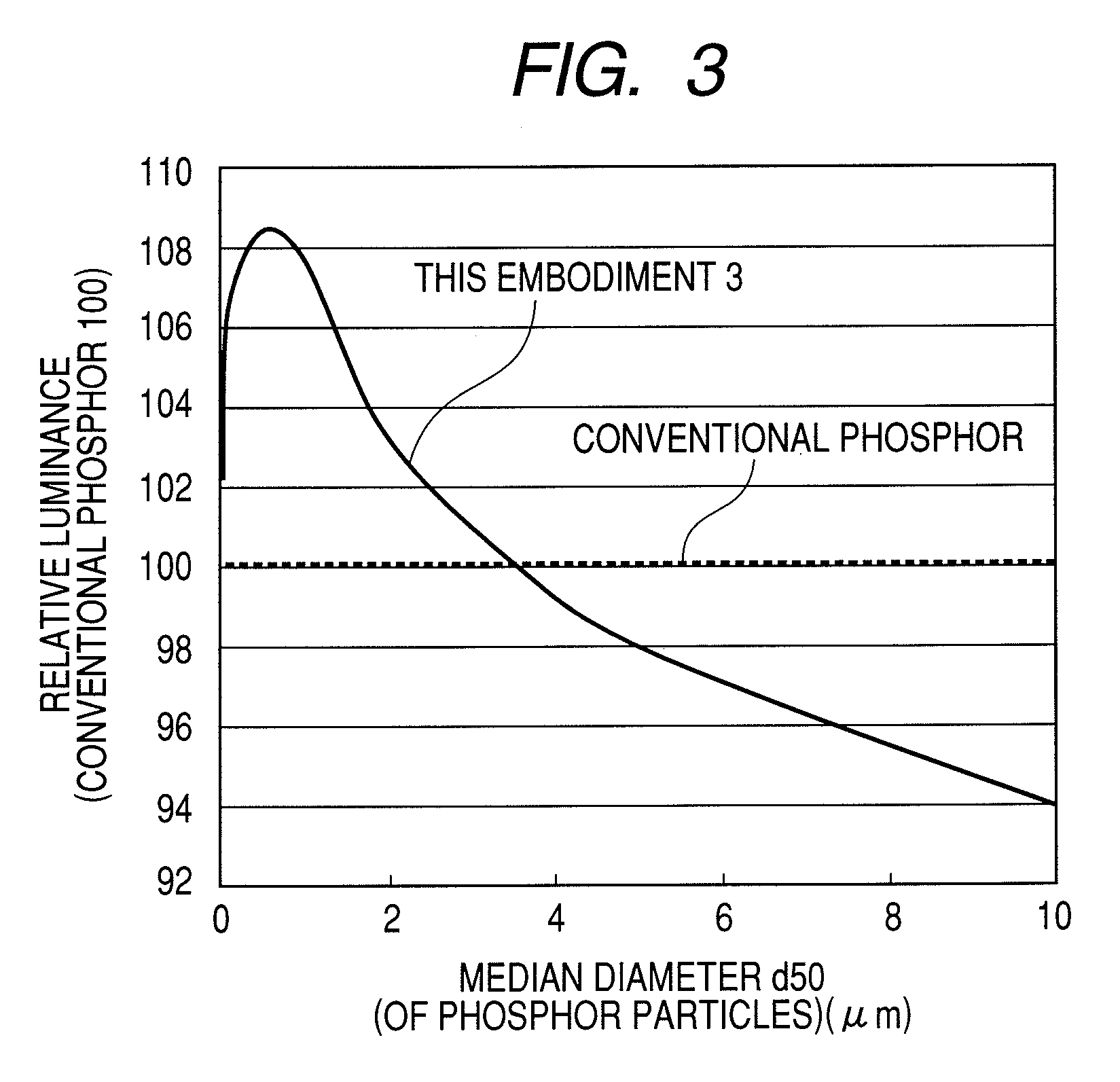
[0063]The third embodiment was produced in the same way as with the first embodiment. A difference between the third embodiment and the first embodiment is that in the third embodiment, two layers of phosphors were formed: one layer was formed by using a single suspension of red phosphor Y2O3: Eu3+; and the other layer by using a suspension mixed with three color phosphors.

[0064]At the time, a layer of the red single color phosphor was evaluated in the property thereof as median diameters d50 thereof were varied within the range of 0.05 μm to 10 μm, in which the median diameters d50 were measured by a “Coulter Counter” (Beckman Coulter, Inc.). Particles of all phosphors including red phosphors, which were used for forming the layer of the mixed color phosphors, had a constant and fixed value of median diameters d50 thereof, the median diameters d50 being in the range of 1.0 μm to 10 μm, in which the median diameters d50 were measured by a coal tar meter.

[0065]According to the third ...


PUM


Abstract

In conventional fluorescent lamps and imaging devices using the same, there have been challenges that lighting efficiency should be enhanced and variation in emission colors should be reduced. The present invention has solved these challenges by providing a novel fluorescent lamp. The phosphor layers of the fluorescent lamp is composed of at least two types of phosphors, in which at least the most outer surface is a phosphor layer made of one of the phosphors (the first phosphor); and the rest portion of the phosphor layers, is made of mixed phosphors including a plurality of phosphors having respective emitting colors.

Description

CLAIM OF PRIORITY[0001]The present application claims priority from Japanese application JP 2007-058911 filed on Mar. 8, 2007, the content of which is hereby incorporated by reference into this application.FIELD OF THE INVENTION[0002]The present invention relates to a phosphor layer with high resolution, long life, high brightness, and good color reproducibility, which is suitable for image display. The present invention also relates to an imaging device using the same, such as a liquid crystal display.BACKGROUND OF THE INVENTION[0003]An imaging device in the present invention means a device in which a phosphor is excited by being given energy to emit a light, resulting in displaying image information. Examples of such imaging devices include a non-self-luminous imaging device which is provided with a light source as a back light or side light, in a non-self-luminous display portion, such as a liquid crystal display panel. The above examples also include a whole system for displayin...

Claims


Application Information

Patent Timeline
IPC IPC(8): H01J1/62G02F1/1335
CPCH01J61/42G02F1/133604
Inventor IMAMURA, SHINOKISHIRO, KENJINISHIKAWA, MASAKI
Owner HITACHI DISPLAYS
Features
  • R&D
  • Intellectual Property
  • Life Sciences
  • Materials
  • Tech Scout
  • Unparalleled Data Quality
  • Higher Quality Content
  • 60% Fewer Hallucinations
Learn More