Methods and systems for fiber optic gyroscopes vibration error suppression

a fiber optic gyroscope and vibration error technology, applied in the field of fiber optic gyroscopes, can solve the problems of poor sensitivity of low rotation rate and generation of rectified bias error, and achieve the effect of removing vibration-induced rotation rate error

Active Publication Date: 2008-09-11
HONEYWELL INT INC
View PDF7 Cites 21 Cited by
  • Summary
  • Abstract
  • Description
  • Claims
  • Application Information

AI Technical Summary

Benefits of technology

[0006]The present invention provides systems and methods for performing vibration error suppression in a fiber optic gyro sensor. An example system includes a light source, a sensing loop assembly, a photo detector, and a processing component. The light source generates a light signal that is applied to a fiber optic coil in the assembly. Light intensity in the optical path of an FOG is modulated in the presence of vibration source. The photo detector receives a modulated light signa

Problems solved by technology

Therefore, because the cosine function is even, the rate of change near zero is very small, resulting in poor sensitiv

Method used


Image

  • Methods and systems for fiber optic gyroscopes vibration error suppression
  • Methods and systems for fiber optic gyroscopes vibration error suppression
  • Methods and systems for fiber optic gyroscopes vibration error suppression

Examples


Embodiment Construction

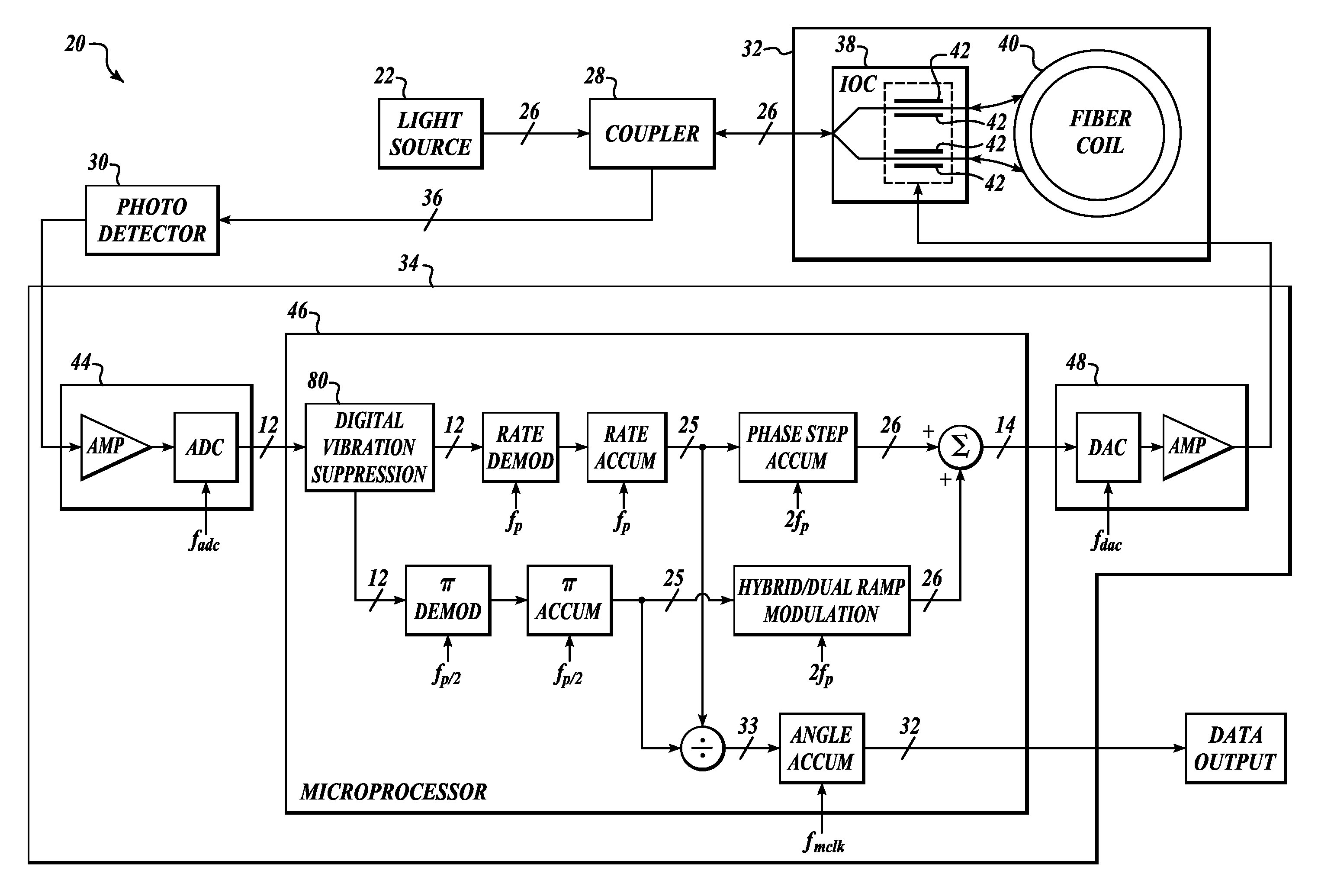
[0014]FIG. 3 illustrates a fiber optic gyroscope system 20 formed according to one embodiment of the present invention. The system 20 includes a light source 22, an optical coupler 28, a photo detector 30, a sensing loop assembly 32, a processing subsystem 34, and fiber optic lines 26, 36 interconnecting various components of the system 20.

[0015]The light source 22 is any light source typically used in fiber optic gyroscopes, such as a Fiber Light Source (FLS) assembly. In one embodiment, the light source includes a 980 nm semiconductor pump laser containing an Erbium doped fiber (EDF) capable of generating light with a wavelength of approximately 1532 nm with an approximate bandwidth of 35 nm.

[0016]In the depicted embodiment, the optical coupler 28 is a 50 / 50 coupler, or splitter, as is commonly understood in the art. The coupler 28 is coupled, via the fiber optic lines 26, to the light source 22, the photo detector 30, and to the sensing loop assembly 32. The coupler 28 receives l...


PUM


Abstract

Systems and methods for performing vibration error suppression in a fiber optic gyro sensor. An example system includes a light source, a sensing loop assembly, a photo detector, and a processing component. The light source generates a light signal that is then modulated by the sensing loop assembly and applied to a fiber optic coil in the assembly. The photo detector receives a modulated light signal that is an output of the sensing loop assembly (coil) and generates an analog signal. The processing component converts the generated analog signal into a modulated digital signal, determines an average of the modulated digital signal, determines an intensity modulation amplitude based on the determined average of the modulated digital signal, and re-scales the modulated digital phase signal based on the determined intensity modulation amplitude.

Description

BACKGROUND OF THE INVENTION[0001]In recent years fiber optic gyroscopes (FOGS) have become widely used in several technologies to sense the rotation and angular orientation of various objects, such as aerospace vehicles. A FOG typically includes an optical fiber, often several kilometers in length, wound in a coil about an axis of rotation (i.e., the rotation to be sensed). Light is injected in opposite directions through the coil and directed onto a photo detector. If the coil is rotated about the axis, the effective optical path length for the light traveling in one direction in the coil is increased, while the path length is decreased for the light traveling in the opposite direction (See FIG. 1).[0002]The difference in path length introduces a phase shift, known as the Sagnac Effect, between the light waves traveling in opposite directions. As a result, an interference pattern is detected by the photo detector, which indicates that the FOG is experiencing rotation. The output si...

Claims


Application Information

Patent Timeline
IPC IPC(8): H04L27/02H03C5/00G01C19/72
CPCG01C19/721
Inventor CHEN, CHUNG-JEN
Owner HONEYWELL INT INC
Why Eureka
Try Eureka