
Switching power supply device

a power supply device and switching technology, applied in the direction of power conversion systems, dc-dc conversion, instruments, etc., can solve the problems of unstable switching operation, reduced efficiency of switching power supply devices, and high cost, and achieves simplified control power supply, high-efficiency switching power supply, and reduced cost

Active Publication Date: 2008-09-11
FUJI ELECTRIC CO LTD
View PDF7 Cites 31 Cited by
  • Summary
  • Abstract
  • Description
  • Claims
  • Application Information

AI Technical Summary

Benefits of technology

[0030]In order to attain the above object, a switching power supply device a series circuit of a first switching element and a second switching element connected in parallel with a DC power supply is provided. A series circuit of a capacitor and primary windings of an isolation transformer is connected in parallel with the second switching element. A rectifying and smoothing circuit, including a rectifying diode and a smoothing capacitor, is connected to secondary windings of the isolation transformer. First and second auxiliary windings are provided to the isolation transformer. A first control circuit is configured to execute control to turn on and off the first switching element based on a voltage generated in the first auxiliary windings. A second control circuit is configured to execute control to turn on and off the second switching element based on a voltage generated in the second auxiliary windings. The first and second switching elements turn on and off alternately, and this results in a DC output from the rectifying and smoothing circuit. The isolation transformer has a configuration in which a wound layer including the primary windings is provided between a layer including the first and second auxiliary windings, and a layer including the secondary windings. In accordance with this invention, when the load increases rapidly and at other times, even when in a mode in which the second switching element turns off before the current flowing in the rectifying diode becomes zero, the first switching element can be turned on at zero voltage. Thus, a switching power supply device that operates stably with low loss and low noise can be provided. Further, an inexpensive switching power supply device can be provided in which a stacked-winding isolation transformer can be used.
[0032]According to a further aspect of the invention, the second control circuit includes a second gate driving circuit configured to turn on and off the second switching element and a time constant circuit that sets the maximum on time of the second switching circuit. The second gate driving circuit causes the second switching element to turn on after a prescribed delay time from the time when the second auxiliary windings voltage changes from negative to positive. It causes the second switching element to turn off at the earlier of the time when the second auxiliary windings voltage switches from positive to negative, and the time after the maximum on time of the second switching element has elapsed, whereby startup failures and simultaneous turning-on of switching elements are avoided.
[0033]According to a still further aspect of the invention, the maximum on time and an excitation inductance value of the isolation transformer are set such that, when a load connected to the DC output is a light load, the second switching element turns off after the current flowing in the rectifying diode becomes zero, and when the load is a heavy load, the second switching element turns off before the current flowing in the rectifying diode becomes zero. Thus, by appropriately setting the excitation inductance of the isolation transformer and the maximum on time of the second switching element, a high-efficiency switching power supply device can be provided.
[0034]According to another aspect of the invention, the voltage generated in the first auxiliary windings of the isolation transformer is rectified and smoothed, and used as the control power supply of the first control circuit. According to still another aspect, the third auxiliary windings are provided in the isolation transformer, a construction is employed in which the wound layer including the secondary windings is provided between the layer including the primary windings and the layer including the third auxiliary windings, and the voltage generated in the third auxiliary windings is rectified and smoothed and is used as the control power supply of the first control circuit. Thus, by rectifying and smoothing the voltage appearing in auxiliary windings to obtain a control power supply, reduced costs through simplification of the control power supply can be achieved.

Problems solved by technology

Because the resulting structure is complex, there is the problem that costs are comparatively high.
As a result, turn-on losses occur, and the efficiency of the switching power supply device is reduced.
Alternatively, the switching operation may become unstable, and unpleasant sounds may be emitted from the isolation transformer.
As a result, there are cases in which an adequate output voltage is not generated and startup fails.

Method used


Image

  • Switching power supply device
  • Switching power supply device
  • Switching power supply device

Examples


Embodiment Construction

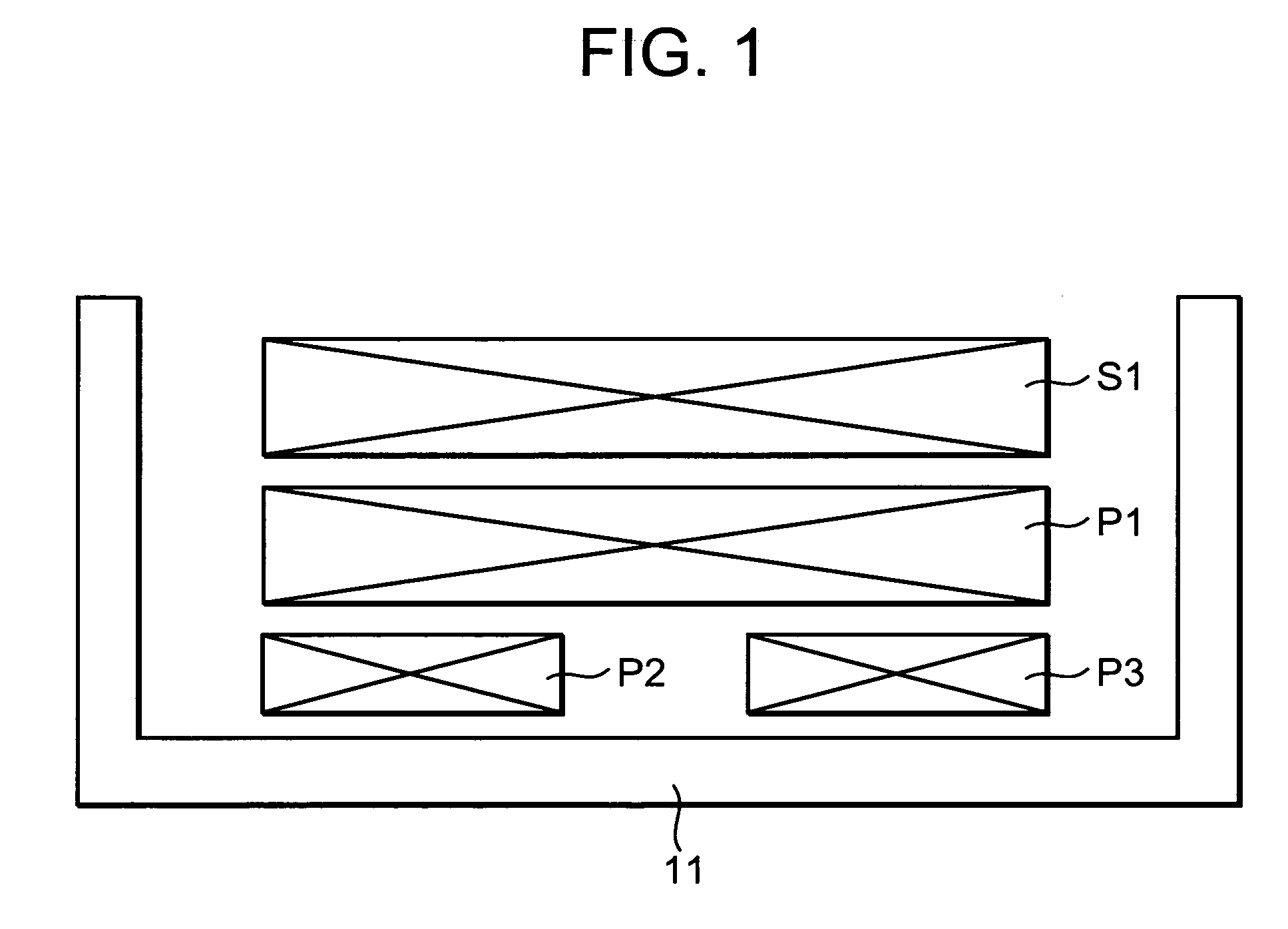
[0054]FIG. 1 shows the winding construction of an isolation transformer, representing a first aspect of the invention based on claim 1. In the winding construction of FIG. 1, a layer including primary windings P1 is wound between a layer including auxiliary windings P2 and P3, and a layer including secondary windings S1; by strengthening the degree of coupling of the auxiliary windings P2, P3 with the primary windings P1 and weakening the degree of coupling with the secondary windings S1, the voltages appearing in the auxiliary windings P2, P3 can be made substantially similar to the voltage appearing in the primary windings P1.

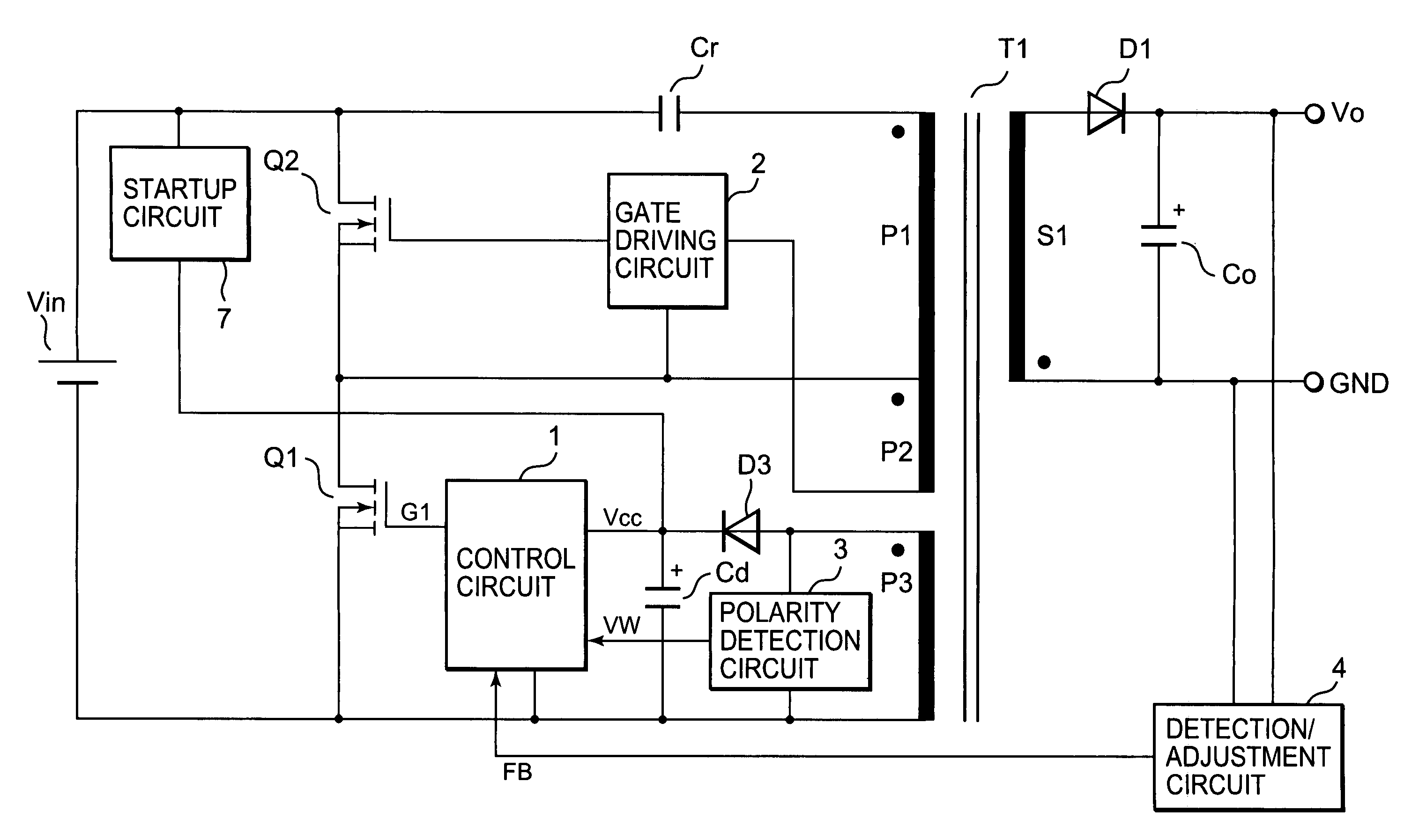
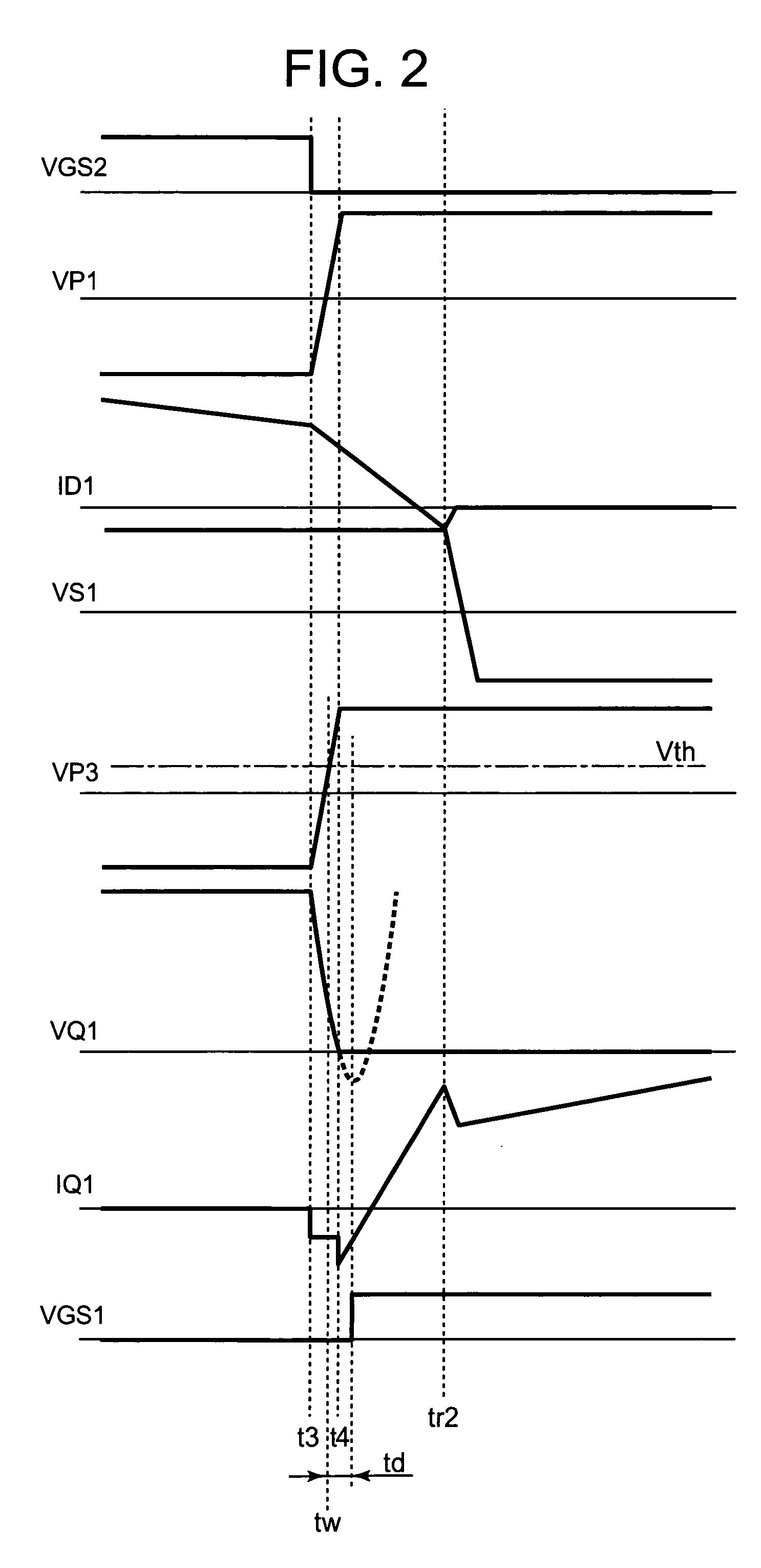
[0055]Below, the waveform diagram of FIG. 2 is used to explain operation when an isolation transformer with the construction of FIG. 1 is applied to the circuit of FIG. 15.

[0056]At time t3, with current flowing in the rectifying diode D1, when the switching element Q2 turns off, VQ2 rises and VQ1 falls. The primary windings voltage VP1 is inverted from negati...


PUM


Abstract

A switching power supply device includes a first series circuit of first and second switching elements connected in parallel with a DC power supply. An isolation transformer has primary and secondary windings and first and second auxiliary windings, a first layer including the primary windings between a second layer of the two auxiliary windings, and a third layer of the secondary windings. A capacitor in series with the primary windings defines a second series circuit in parallel with the second switching element. A rectifying and smoothing circuit includes a rectifying diode and a smoothing capacitor, connected to the secondary windings. First and second control circuits turn on and off the first and second switching elements based on voltages generated in the two auxiliary windings, to obtain a DC output from the rectifying and smoothing circuit, enabling an adequate auxiliary windings voltage and stable switching operation including stable zero-voltage turn-on.

Description

BACKGROUND OF THE INVENTION[0001]1. Field of the Invention[0002]The invention relates to a switching power supply device, which controls on / off switching of a switching element based on a voltage occurring in auxiliary windings provided in an isolation transformer, and which obtains a DC output insulated from a DC power supply.[0003]2. Description of the Related Art[0004]FIG. 13 shows technology of the prior art for this type of switching power supply device, with a circuit configuration which is substantially the same as that of the switching power supply devices disclosed in Japanese Patent Laid-open No. 2001-231258, FIGS. 1 and 10 (corresponding to U.S. Pat. No. 6,362,984) and in Japanese Patent Laid-open No. 2002-209381, FIG. 1 (corresponding to U.S. Pat. No. 6,483,722). In this circuit, by alternately turning on and off the switching element Q1 and switching element Q2 based on the voltage appearing in two auxiliary windings P2, P3 provided in the isolation transformer T1, a re...

Claims


Application Information

Patent Timeline
IPC IPC(8): H02M3/335
CPCH02M7/003H02M3/33569H02M3/33571H02M3/01
Inventor NISHIKAWA, YUKIHIRO
Owner FUJI ELECTRIC CO LTD
Features
  • Generate Ideas
  • Intellectual Property
  • Life Sciences
  • Materials
  • Tech Scout
  • Unparalleled Data Quality
  • Higher Quality Content
  • 60% Fewer Hallucinations
Learn More