Quantum cascade laser

Active Publication Date: 2008-09-11
HAMAMATSU PHOTONICS KK
View PDF5 Cites 30 Cited by
  • Summary
  • Abstract
  • Description
  • Claims
  • Application Information

AI Technical Summary

Benefits of technology

[0018]In the above-described quantum cascade laser, in the subband level structure in the unit laminate structure formed of the quantum well light emitting layer and injection layer, in addition to the emission upper level and the emission lower level relating to emission, an injection level is provided as an energy level higher than the emission upper level. Then, electrons from the unit laminate structure of the preceding stage are not directly injected into the emission upper level, but are injected into the injection level and then relaxed and supplied to the emission upper level. Thereby, the supply efficiency of electrons to the emission upper level can be improved, and operation of the quantum cascade laser with a high output at a high temperature is realized. Such a subb

Problems solved by technology

In a semiconductor laser with a conventional structure, it is difficult to lengthen the wavelength to such a terahertz region.
However, at present, the operation of the quantum cascade laser in the terahertz region is limited to the operation in an extremely low-temperature environment using liquid nitrogen, and its laser output is as low as 1 mW or less, so that its performance is not sufficient as a light source.
As a result, it was found that

Method used


Image

  • Quantum cascade laser
  • Quantum cascade laser
  • Quantum cascade laser

Examples


Embodiment Construction

[0031]Hereinafter, preferred embodiments of a quantum cascade laser of the present invention will be described in detail with reference to the drawings. In the description of the drawings, the same components are attached with the same reference numerals, and overlapping description will be omitted. The dimensional ratios of the drawings are not always equal to those of the description.

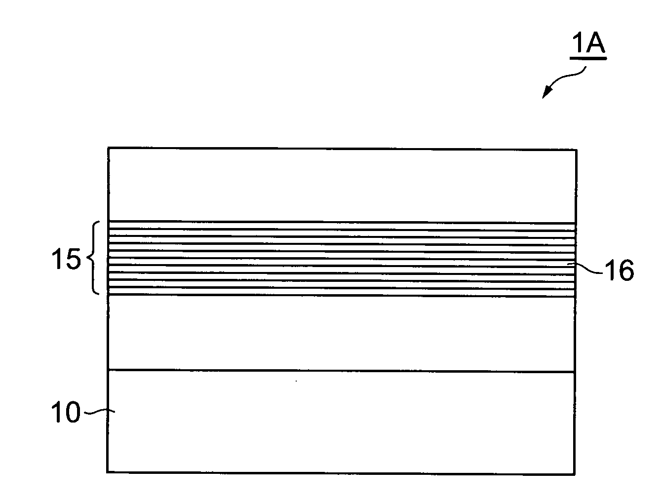
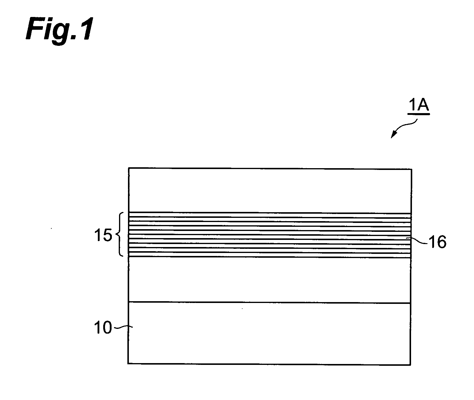
[0032]FIG. 1 is a view schematically showing a basic configuration of a quantum cascade laser of the present invention. The quantum cascade laser 1A of this embodiment is a monopolar type laser element which generates light by using electron transition between subbands in a semiconductor quantum well structure. This quantum cascade laser 1A is composed of a semiconductor substrate 10 and an active layer 15 formed on the semiconductor substrate 10. On two predetermined surfaces opposite to each other among side surfaces of the quantum cascade laser 1A, mirror surfaces (not shown) forming optical resona...


PUM


Abstract

A quantum cascade laser is composed of a semiconductor substrate, and an active layer provided on the semiconductor substrate and having a cascade structure formed by multistage-laminating unit laminate structures 16 each of which includes a quantum well light emitting layer 17 and an injection layer 18. The unit laminate structure 16 has, in its subband level structure, an emission upper level 3, an emission lower level 2, and an injection level 4 as an energy level higher than the emission upper level 3, and light hν is generated by means of intersubband transition of electrons from the level 3 to the level 2 in the light emitting layer 17, and electrons through the intersubband transition are injected into the injection level in a unit laminate structure of the subsequent stage via the injection layer 18, and from this injection level, electrons are supplied to the emission upper level. Thereby, a quantum cascade laser which realizes operation with a high output at a high temperature is realized.

Description

BACKGROUND OF THE INVENTION[0001]1. Field of the Invention[0002]The present invention relates to a quantum cascade laser using intersubband transition in a quantum well structure.[0003]2. Related Background Art[0004]Light in a mid-infrared wavelength range (for example, wavelength of 5 to 30 μm) is an important wavelength range in the field of spectroanalysis. As a high-performance semiconductor light source in this wavelength range, recently, a quantum cascade laser (QCL) has gained attention (regarding the quantum cascade laser, refer to, for example, Patent documents 1 to 5 and Non-patent documents 1 and 2 listed below).[0005]The quantum cascade laser is a monopolar type laser element which generates light by means of electron transition between subbands by using a level structure formed by subbands in a semiconductor quantum well structure, and high efficiency and high output operation can be realized by multistage cascade coupling of quantum well light emitting layers that are ...

Claims


Application Information

Patent Timeline
IPC IPC(8): H01S5/10
CPCB82Y20/00H01S5/22H01S2302/02H01S5/3415H01S5/3432H01S5/3402
Inventor YAMANISHI, MASAMICHIEDAMURA, TADATAKAAKIKUSA, NAOTAFUJITA, KAZUUE
Owner HAMAMATSU PHOTONICS KK
Why Eureka
Try Eureka