Magnetic resonance imaging of coronary venous structures

a magnetic resonance imaging and coronary venous technology, applied in the field of magnetic resonance imaging of coronary venous structures, can solve the problems of inapplicability of conventional coronary mri methods, inability to use established contrast preparation sequences based on tsub>2 /sub>, and inability to achieve the effect of enhancing the contrast between venous blood and myocardium, suppressing coronary vein signals, and improving blood-myocardial contras

Inactive Publication Date: 2008-09-11
BETH ISRAEL DEACONESS MEDICAL CENT INC
View PDF48 Cites 11 Cited by
  • Summary
  • Abstract
  • Description
  • Claims
  • Application Information

AI Technical Summary

Benefits of technology

[0007]In one aspect, the present invention relates to a high-resolution coronary magnetic resonance vein imaging sequence that can be advantageously utilized as part of a 3D free-breathing, ECG-triggered gradient-echo Cartesian acquisition of the coronary region. In coronary artery imaging, typically a T2 preparation sequence is used to improve blood-myocardium contrast. However, this preparation sequence suppresses coronary vein signals due to the short T2 of deoxygenated coronary venous blood (T2=35 milliseconds).
[0008]The present invention utilizes at least one magnetization transfer (MT) prepulse to enhance the contrast between venous blood and myocardium. The MT preparation results in myocardial signal suppression without any significant signal loss in the arterial or venous blood so as to maintain venous blood signal-to-noise rat...

Problems solved by technology

Although there are significant similarities between coronary artery and vein imaging using magnetic resonance, there are also considerable differences.
However, coronary venous blood has a short T2 relaxation time compared to arterial blood, which makes the use of es...

Method used


Image

  • Magnetic resonance imaging of coronary venous structures
  • Magnetic resonance imaging of coronary venous structures
  • Magnetic resonance imaging of coronary venous structures

Examples


Embodiment Construction

[0029]A description of example embodiments of the invention follows.

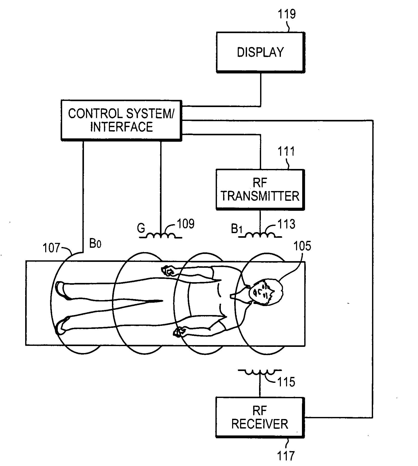
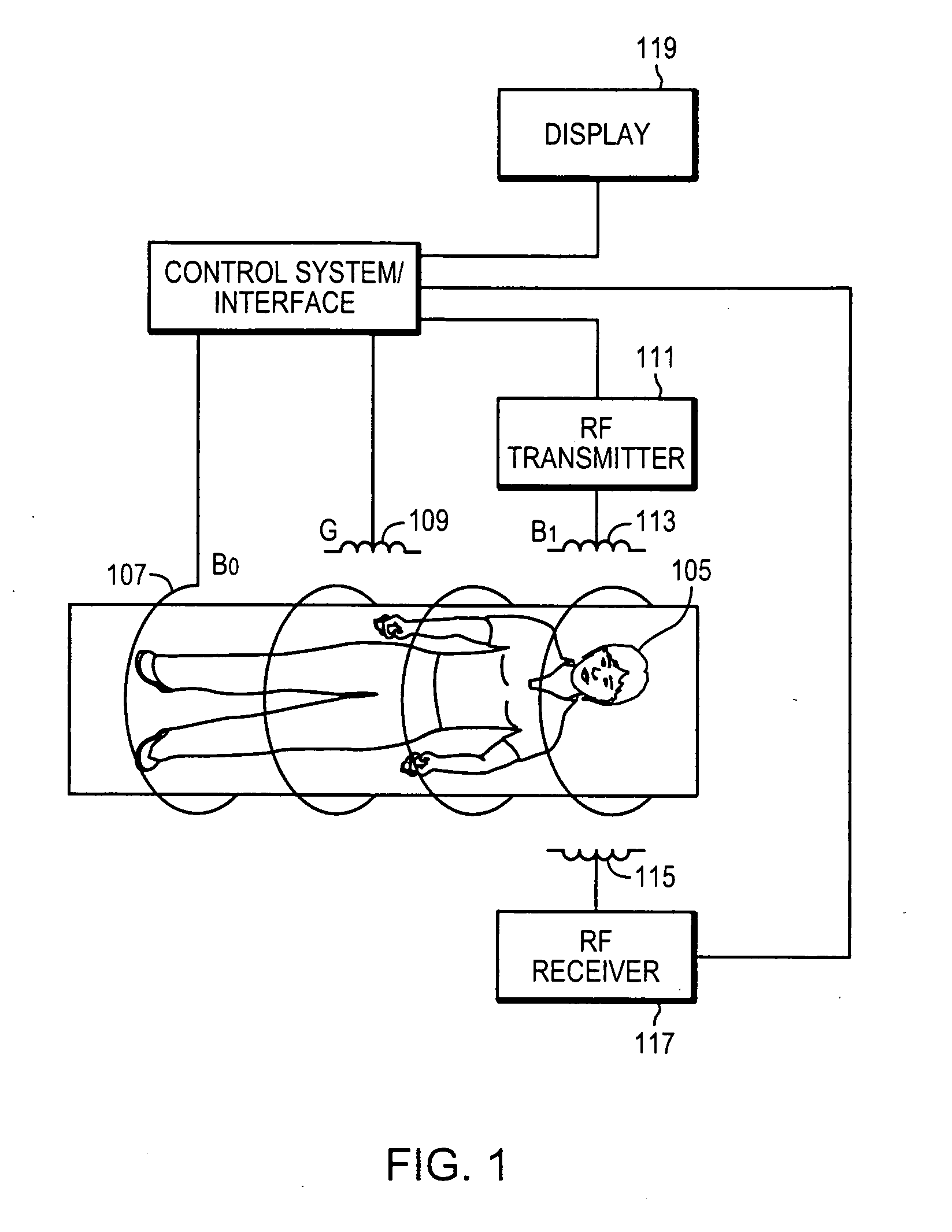
[0030]A representative magnetic resonance imaging (MRI) system 101 is shown in FIG. 1. The system includes a control system / interface 103 that is programmed with a series of commands to perform a sequence of imaging steps. The controller 103 controls a field coil 107 for producing a stationary magnetic field B0, one or more gradient coils 109 for producing gradient magnetic fields, G, and a radiofrequency (RF) transmitter 111 configured to generate RF pulses that are applied to a transmitter coil 113 to produce an RF magnetic field, B1. A receiver coil 115 detects changes in the magnetization of the object being imaged, and transmits these signals to an RF receiver 117. The receiver 117 converts these signals into electrical signals that can be processed by the control system 103 to produce an image of an object 105 located within the MRI system. The image can be viewed on a display apparatus 119.

[0031]The principle...


PUM


Abstract

A method and system for magnetic resonance imaging comprises applying at least one radiofrequency magnetization transfer (MT) pulse to a coronary venous region of a subject positioned within a magnetic field, and acquiring magnetic resonance imaging data from the coronary venous region to produce an image of a coronary venous structure. This technique can be utilized as part of a 3D free-breathing, ECG-triggered gradient-echo Cartesian acquisition of the coronary region. One or more magnetization transfer (MT) preparation pulses are used to enhance the contrast between venous blood and myocardium. The MT preparation results in myocardial signal suppression without any significant signal loss in the arterial or venous blood so as to maintain venous blood signal-to-noise ratio while improving contrast between myocardium and veins. The coronary venous structure can comprise one or more of a coronary sinus, a lateral vein and a posterior vein. The image of a coronary venous structure can be acquired in connection with an interventional cardiovascular procedure, such as a cardiac resynchronization therapy.

Description

RELATED APPLICATION[0001]This application claims the benefit of U.S. Provisional Application No. 60 / 898,975 filed on Feb. 1, 2007.[0002]The entire teachings of the above application are incorporated herein by referenceBACKGROUND OF THE INVENTION[0003]Knowledge of coronary vein anatomy is becoming increasingly important for diagnostic and interventional cardiac procedures including epicardial radiofrequency ablation, retrograde perfusion therapy in high-risk or complicated coronary angioplasty, arrhythmia assessment, stem cell delivery, coronary artery bypass surgery and cardiac resynchronization therapy (CRT). Congestive heart failure currently afflicts over 5 million Americans. In patients with severe congestive heart failure, CRT has been proven as an adjuvant therapy to pharmacological treatment. In CRT, simultaneous pacing of the right ventricle and left ventricle, or pacing the left ventricle alone, results in hermodynamic improvements and restoration of a more physiological co...

Claims


Application Information

Patent Timeline
IPC IPC(8): A61B5/055
CPCA61B5/055G01R33/5605G01R33/5607G01R33/5676G01R33/56509G01R33/5673G01R33/5635
Inventor NEZAFAT, REZAMANNING, WARREN
Owner BETH ISRAEL DEACONESS MEDICAL CENT INC
Why Eureka
Try Eureka