Advanced internal combustion engine

Active Publication Date: 2008-09-18
MARO PERFORMANCE GROUP
View PDF17 Cites 46 Cited by
  • Summary
  • Abstract
  • Description
  • Claims
  • Application Information

AI Technical Summary

Problems solved by technology

However, since such an adjustment prevents complete combustion, increased amounts of unburned hydrocarbons and carbon m

Method used


Image

  • Advanced internal combustion engine
  • Advanced internal combustion engine
  • Advanced internal combustion engine

Examples


Embodiment Construction

I. System Definitions

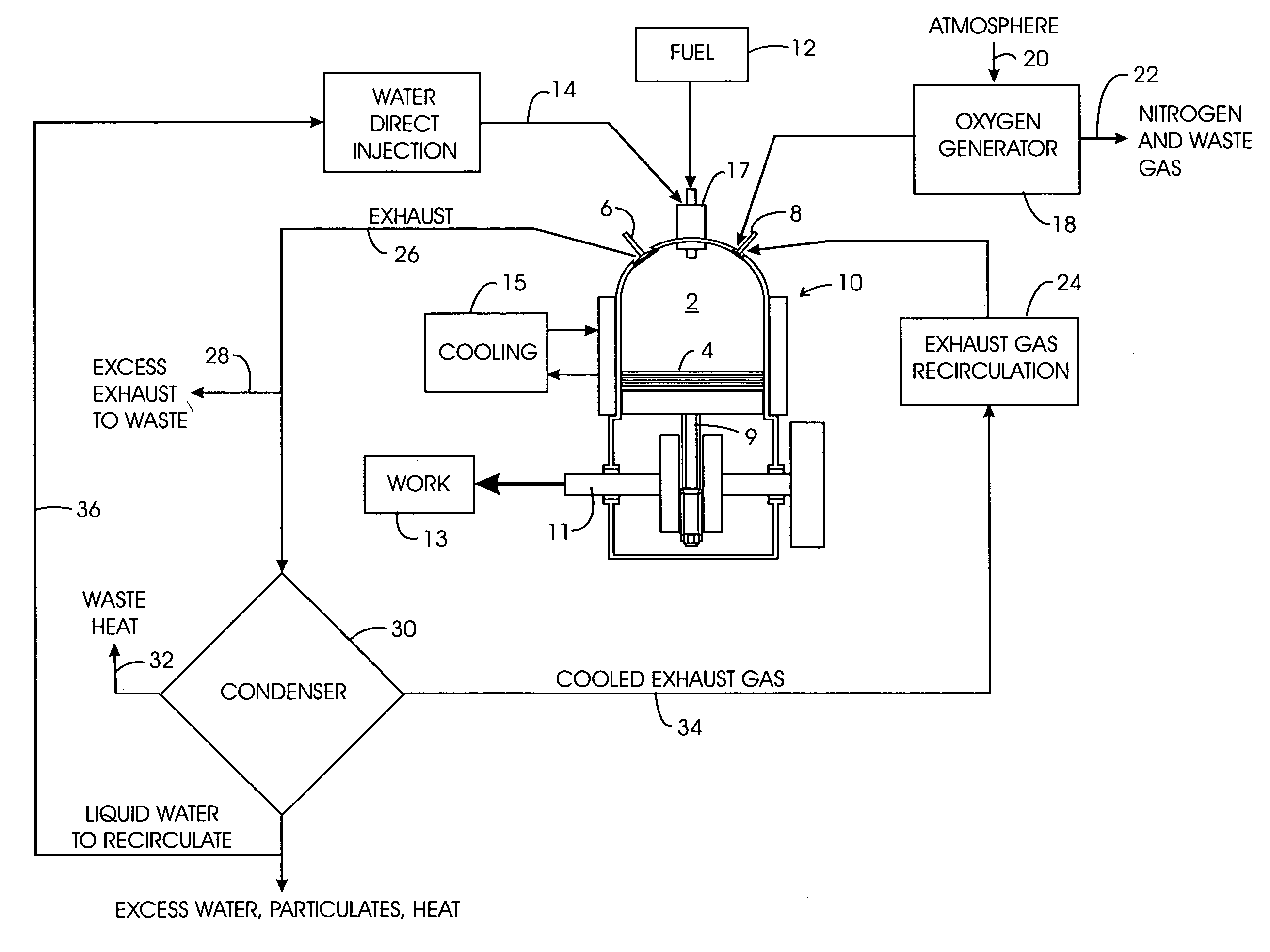
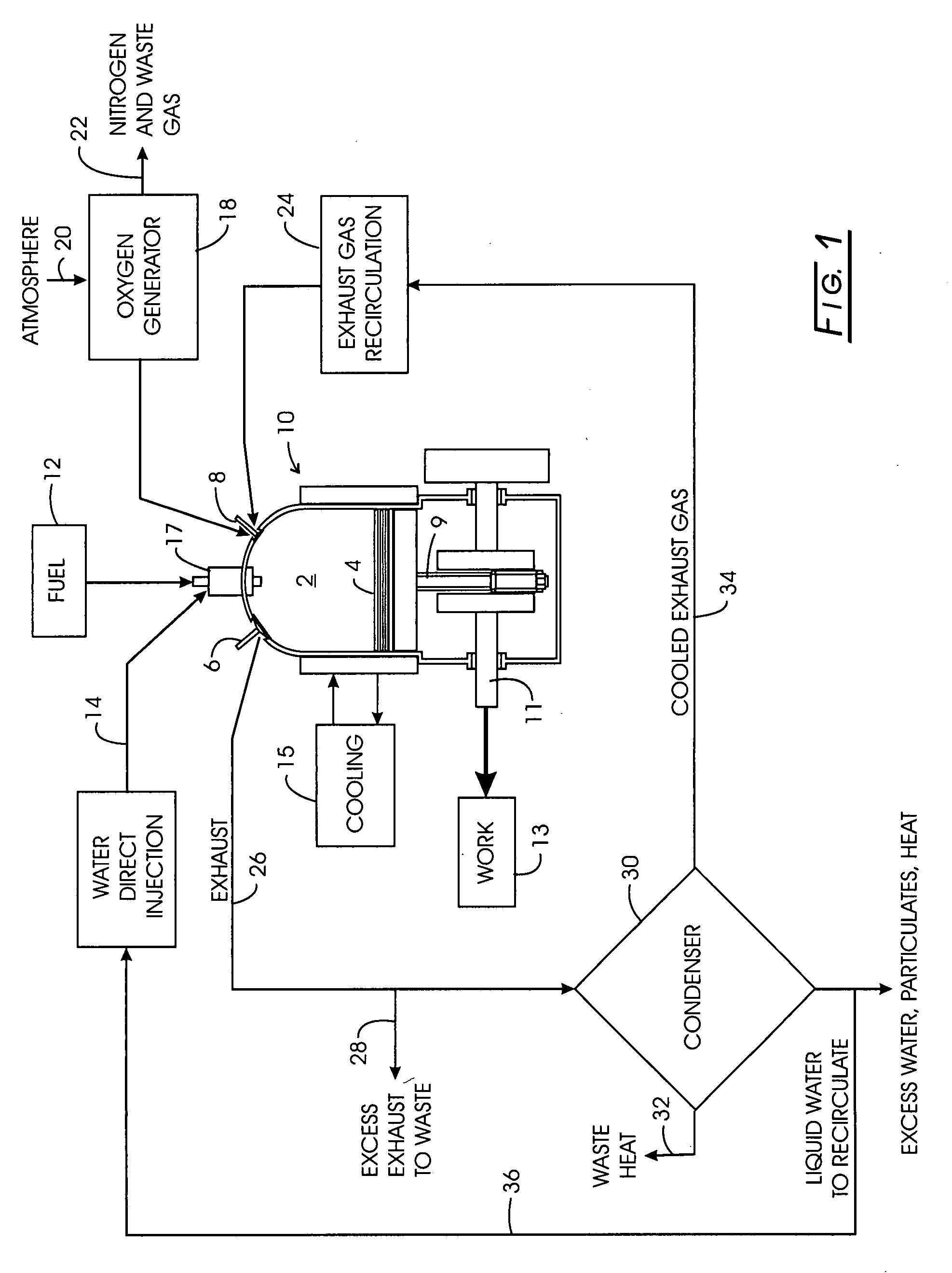
[0031]A founding hypothesis of this disclosure is the idea that the performance characteristics of an internal combustion engine relative to power output, fuel efficiency, and exhaust emissions can be significantly altered (enhanced) by removing a significant portion of the nitrogen gas from the intake air delivered to the combustion chamber.

1. Oxygen Generator and Intake System

[0032]The first component of the system is a unit that can admit atmospheric air and divide its output into a stream of (ostensible pure or ˜95% purity) oxygen (molecular oxygen or O2) and another separate stream of gases (mostly Nitrogen, N2) other than oxygen. The purpose of this step is to provide to an engine an inlet air stream that is ostensibly pure oxygen, or to a lesser extent highly oxygen enriched compared to atmospheric air typical to engine intake. The idea is to remove, within practical limits, all of the nitrogen content from the inlet air stream into the engine, recognizin...


PUM


Abstract

An internal combustion engine power cycle wherein a combustion chamber is fitted with an inlet valve, an outlet valve, and movable piston coupled to perform work, includes an generator to form a stream of greater than about 95% molecular oxygen from atmospheric air and a nitrogen waste gas stream; a source of fuel; and a source of liquid water. The power cycle includes admission of the molecular oxygen into the chamber, injection of the fuel into the chamber with combustion, and injection of atomized water into the chamber for generation of steam.

Description

CROSS-REFERENCE TO RELATED APPLICATIONS[0001]NoneSTATEMENT REGARDING FEDERALLY SPONSORED RESEARCH[0002]Not applicable.BACKGROUND[0003]The present invention generally relates to internal combustion engines and more particularly to an internal combustion engine (both two-stroke and 4-stroke engines) that uses directly injected molecular oxygen, viz., O2, with concomitant suppression of by-product N2, NOx gases (herein often referred to as “nitrogen gases”).[0004]The overall efficiency of an internal combustion engine, or simply “engine” for present purposes, depends in part on the amount of fuel that can be burned in any given cycle. In recent years, environmental concerns have had an increasing effect on such engines. For example, the air / fuel mixture fed into the engine typically is adjusted to prevent complete combustion so that the catalytic converter will be able to reduce emitted nitrogen oxides to the level required by governmental standards. However, since such an adjustment p...

Claims


Application Information

Patent Timeline
IPC IPC(8): F02B47/02
CPCF02B43/10F02B47/02F02M25/03F02M25/0222Y02T10/121Y02T10/32F02M25/0227F02M25/0727F02B47/10F02M26/23Y02T10/12Y02T10/30
Inventor MARO, RANDALL A.MATOUSEK, ROBERT A.
Owner MARO PERFORMANCE GROUP
Why Eureka
Try Eureka