Low leakage plunger assembly for a high pressure fluid system

a high-pressure fluid and plunger technology, which is applied in the direction of fuel injection apparatus, charge feed system, engine seals, etc., can solve the problems of reducing engine efficiency, reducing the efficiency of high-pressure fuel, and recent loss of high-pressure fuel, so as to reduce fluid leakage, reduce energy consumption, and maximize efficiency

Inactive Publication Date: 2008-09-18
CUMMINS INC
View PDF23 Cites 41 Cited by
  • Summary
  • Abstract
  • Description
  • Claims
  • Application Information

AI Technical Summary

Benefits of technology

[0013]One advantage of the present invention, therefore, is in providing an improved fluid control device capable of optimally minimizing fuel leakage between the plunger and the barrel, thus increasing efficiency.
[0014]Another advantage of the present invention is in providing an improved fluid control device which can be applied to either a valve or a pump to effectively reduce fluid leakage between the pump or valve member and its body forming a bore.
[0015]Yet another advantage of the present invention is in providing an improved fluid control device which can be applied to fuel pumps, including unit fuel injectors and reciprocating plunger type pumps positioned upstream from a fuel injector in a high pressure f

Problems solved by technology

Specifically, any leakage of high pressure fuel within the fuel system represents wasted energy that can reduce engine efficiency.
Loss of high pressure fuel has recently become an even greater problem as injection pressure levels are increased in an effort to improve fuel economy and reduce emissions as required by recent and upcoming legislation.
However, the practice of requiring closer tolerances increases manufacturing costs.
However, this method undesirably increases the size and weight of the components and, thus, the fuel system.
However, these references do not suggest reducing the leakage between the plunger and adjacent bore wall and, therefore, are subject to the disadvantages discussed hereinabove.
Although deformation of t

Method used


Image

  • Low leakage plunger assembly for a high pressure fluid system
  • Low leakage plunger assembly for a high pressure fluid system
  • Low leakage plunger assembly for a high pressure fluid system

Examples


Embodiment Construction

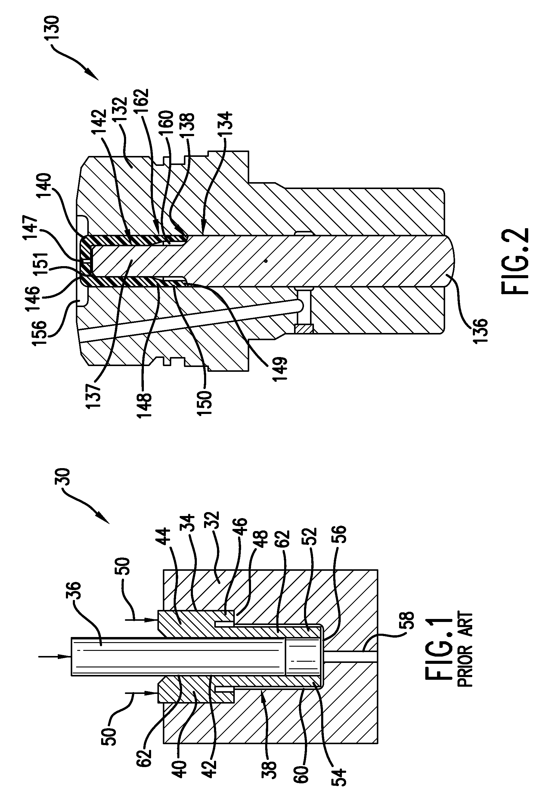
[0039]FIG. 1 is provided to clearly show the primary differences of the fluid control device of the present invention, when incorporated into a fuel pump, as compared to other fuel pumps that use known sealing sleeves. The prior art plunger and barrel assembly of FIG. 1 is shown as applied to a fuel pump 30. The fuel pump 30 includes a body or barrel 32 having a cavity 34 formed therein, a plunger 36 mounted for reciprocal movement in the cavity 34, and a leakage flow reduction device 38 mounted between the plunger 36 and the barrel 32. The leakage flow reduction device 38 includes a sealing sleeve 40, with a bore 42 for receiving the plunger 36 and an outer portion 44 with an annular step 46 for sealingly abutting an annular land 48 formed on barrel 32. The sealing sleeve 40 is rigidly held in place in the cavity 34 by axial clamping forces 50. The sealing sleeve 40 also includes an inner flexible portion 52, an inner end 54 of which terminates at a spaced distance from the inner e...


PUM


Abstract

A fluid control device for use in a high pressure fluid system, the device including a device body with a cavity and a high pressure circuit, a plunger positioned for reciprocal movement in the cavity, and a leakage reduction cap mounted to the plunger for reducing fluid leakage flow. In one implementation, the leakage reduction cap includes a flexible portion positioned between the device body and the plunger, and defining an annular clearance gap between the leakage reduction cap and the device body. The flexible portion of the leakage reduction cap resiliently flexes radially outwardly in response to fluid pressure forces to reduce the annular clearance gap so as to minimize fluid leakage flow through the annular clearance gap.

Description

[0001]This application claims priority to U.S. Provision application No. 60 / 907,035, filed Mar. 16, 2007BACKGROUND OF THE INVENTION[0002]1. Field of the Invention[0003]This invention relates to a plunger and barrel assembly for a fluid system which effectively minimizes leakage through a clearance between the plunger and the barrel assembly.[0004]2. Description of the Related Art[0005]Engine designers are continually seeking improvements in engine design which improve engine efficiency. One manner of improving engine efficiency is to improve the operational efficiency of the fuel system. Specifically, any leakage of high pressure fuel within the fuel system represents wasted energy that can reduce engine efficiency. Loss of high pressure fuel has recently become an even greater problem as injection pressure levels are increased in an effort to improve fuel economy and reduce emissions as required by recent and upcoming legislation.[0006]Undesirable leakage of fuel often occurs in a ...

Claims


Application Information

Patent Timeline
IPC IPC(8): F16J15/00
CPCF02M59/442F02M59/02
Inventor BENSON, DONALD J.BUCHANAN, DAVID L.SIMMONS, SCOTT R.
Owner CUMMINS INC
Why Eureka
Try Eureka