Electric Machine and Manufacturing Process for Same

a manufacturing process and technology for electric machines, applied in the direction of windings, dynamo-electric components, synchronous machines, etc., can solve the problems of reducing the performance of electrical insulation provided, difficult to manage the bends disposed at the inside difficult to view from the outside-diametral side of the core, so as to reduce the performance of electrical insulation performance, improve the mounting efficiency of each winding, and facilitate managemen

Inactive Publication Date: 2008-09-18
HITACHI LTD
View PDF0 Cites 13 Cited by
  • Summary
  • Abstract
  • Description
  • Claims
  • Application Information

AI Technical Summary

Benefits of technology

[0015]According to the foregoing typical aspect of the present invention, the plurality of unit windings can be inserted from one end of the core into the plurality of slots thereof and since the plurality of unit windings can be connected at the other end of the core, mounting the windings around the core does not require a large number of man-hours. In addition, according to the foregoing typical aspect of the present invention, point contact between the core and one of the two conductor lead-out portions at the crossover-side conductor end can be made less prone to occur when the windings are mounted around the core, and appropriate mounting of the windings around the core can be achieved just by managing point contact between the core and one of the two conductor lead-out portions at the crossover-side conductor end.

Problems solved by technology

This is considered to reduce performance of electrical insulation provided at the bend (twisted portion) of the winding end.
However, the two bends disposed at inside-diametral and outside-diametral sides of the core are difficult to manage at the same time.
In addition, the bend disposed at the inside-diame

Method used


Image

  • Electric Machine and Manufacturing Process for Same
  • Electric Machine and Manufacturing Process for Same
  • Electric Machine and Manufacturing Process for Same

Examples


first embodiment

[0038]A first embodiment of the present invention will be described in accordance with FIGS. 1 to 8.

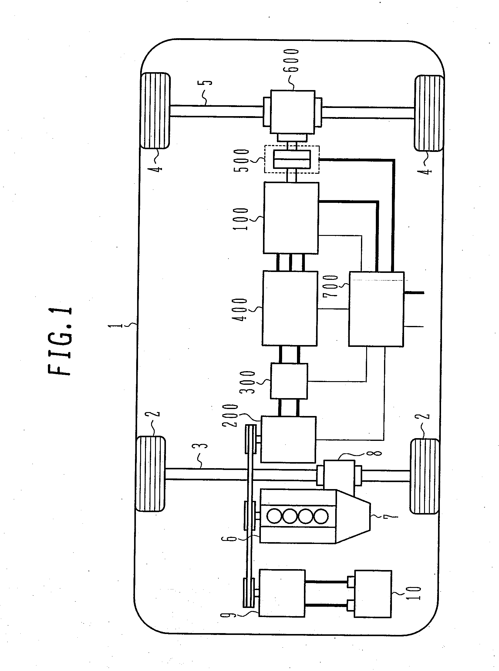
[0039]First, a driving system configuration of a four-wheel drive hybrid electric vehicle without a motor-driving battery is described below using FIG. 1.

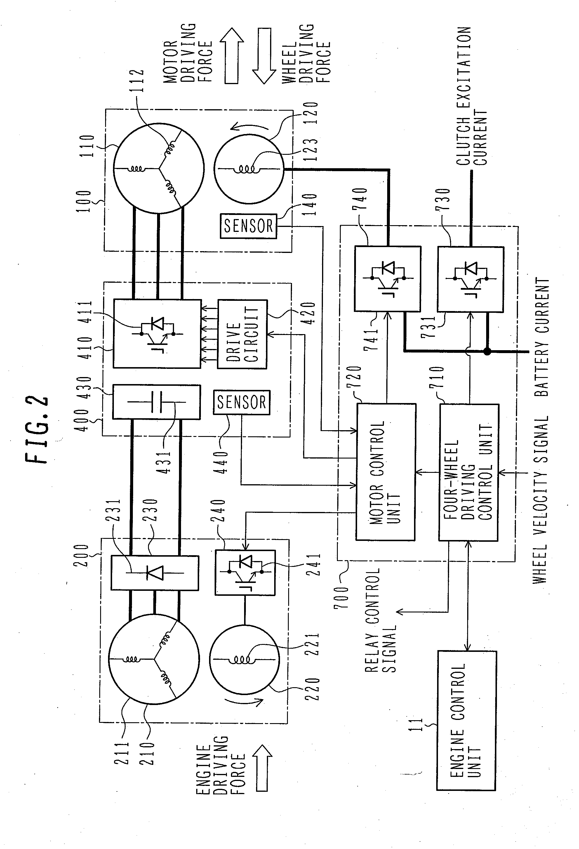
[0040]In FIG. 1, a control cable for transmitting control signals is shown with a thin solid line, and an electrical cable for supplying electrical energy is shown with a solid line thicker than the solid line denoting the control cable. These also apply to FIG. 2 described later herein.

[0041]The four-wheel drive hybrid electric vehicle without a motor-driving battery (four-wheel drive vehicle 1) is a composite drive vehicle that includes a driving system based on an internal combustion engine 6, and a driving system based on a motor 100 which is a rotary electric machine. The vehicle activates the engine 6 to drive front wheels 2 (main wheels) and activates the motor 100 to drive rear wheels 4 (follower wheels). The engine 6 is a mo...

second embodiment

[0191]A second embodiment of the present embodiment will be described in accordance with FIGS. 9 to 11.

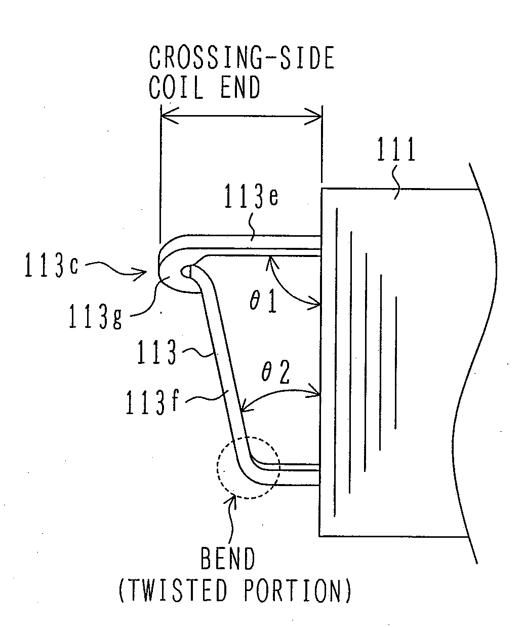
[0192]The present embodiment is an improvement on the first embodiment, and in the present embodiment, the crossover side portions of the connecting-side coil end 113d are formed similarly to those of the crossover-side coil end 113c. That is to say, the crossover side portion 113i is a rectilinear portion extending rectilinearly from the other lateral end of the side portion 113b (i.e., the side opposite to the crossover side portion 113f), towards the side opposite to the crossover side portion 113f. The crossover side portion 113h is an inclined portion extending from the other lateral end of the side portion 113a (i.e., the end opposite to the crossover side portion 113e), in a direction of the end opposite to the crossover side portion 113e (i.e., the direction in which the crossover side portion axially is away from the stator core 111), while the same extends in a direction ...


PUM

PropertyMeasurementUnit
Lengthaaaaaaaaaa
Angleaaaaaaaaaa
Shapeaaaaaaaaaa

Abstract

To provide an electric machine capable of being improved in both fabricability and reliability, and a process for manufacturing the machine.
In order to ensure resolution of the above subject, a stator coil 112 is constructed from a plurality of coil conductors 113 each mounted in two spaced slots 111b, each of the coil conductors 113 is formed under a no-end state at any portions from a connection 113j to a connection 113k, and a crossover-side coil end 113c that includes crossover side portions 113e and 113f crossing over from one of two spaced slots 111b to the other of the slots, guided from an end of a stator core 111 outside the outside of the stator core, and extending in the direction that the crossover side portion is away from the end of the stator core 111 is formed so that an angle of a crossover side of the crossover side portion 113e with respect to an edge present at the end of the stator core 111 is greater than an angle of a crossover side of the crossover side portion 113f with respect to the edge present at the end of the stator core 111.

Description

BACKGROUND OF THE INVENTION[0001]1. Field of the Invention[0002]The present invention relates to an electric machine and a manufacturing process for the same, and typically, to a technique for improving fabricability and reliability of an electric machine having a winding.[0003]2. Description of the Related Art[0004]Known existing techniques relating to an electric machine with a winding are disclosed in JP-A-2001-298888 or JP-A-2001-37131, for example.[0005]JP-A-2001-298888 discloses a technique for constructing a stator coil of an alternating-current power generator for a motor vehicle by using a U-shaped segment coil.[0006]JP-A-2001-37131 discloses a technique for constructing a stator coil of an alternating-current power generator for a motor vehicle by using a coil piece that includes a first rectilinear portion, a second rectilinear portion connected to the first rectilinear portion via a single bend, and a third rectilinear portion connected to the second rectilinear portion ...

Claims


Application Information

Patent Timeline
IPC IPC(8): H02K3/12H02K15/085
CPCY10T29/49009H02K3/505
Inventor YOSHIDA, KENICHIOYAMA, KAZUTOSHIMIZU, HISAYAUMESAKI, YOSUKE
Owner HITACHI LTD
Why Eureka
Try Eureka