
Method and apparatus to control electric power consumption

Active Publication Date: 2008-09-18
FORD GLOBAL TECH LLC
View PDF11 Cites 29 Cited by
  • Summary
  • Abstract
  • Description
  • Claims
  • Application Information

AI Technical Summary

Benefits of technology

[0009]In one non-limiting embodiment, a system and method is provided for controlling the electrical power consumption of an accessory device in a vehicle having an engine, a battery and a power transmission unit are provided. The power transmission unit is adapted to generate electrical power. The system comprises a first controller, a current sensor and a second controller. The first controller is adapted to control the operation of the accessory device. The current sensor is configured to measure an amount of current being charge

Problems solved by technology

As a result, select electrical accessory devices may be shut down or limited for periods of time with the intent of making more power available to meet the needed wheel torque demand.
Such high wheel torque demands may involve instances in which the vehicle is quickly accelerating, or when the vehicle is climbing a hill.
While conventional methods control the usage of electrical accessory devices without considering the source of the power being used, such an approach may not be efficient since an energy loss may be attributed to storing electrical power in the battery and then using the stored power as opposed to directly using power generated by the engine or regenerative braking.

Method used


Image

  • Method and apparatus to control electric power consumption
  • Method and apparatus to control electric power consumption
  • Method and apparatus to control electric power consumption

Examples


Embodiment Construction

)

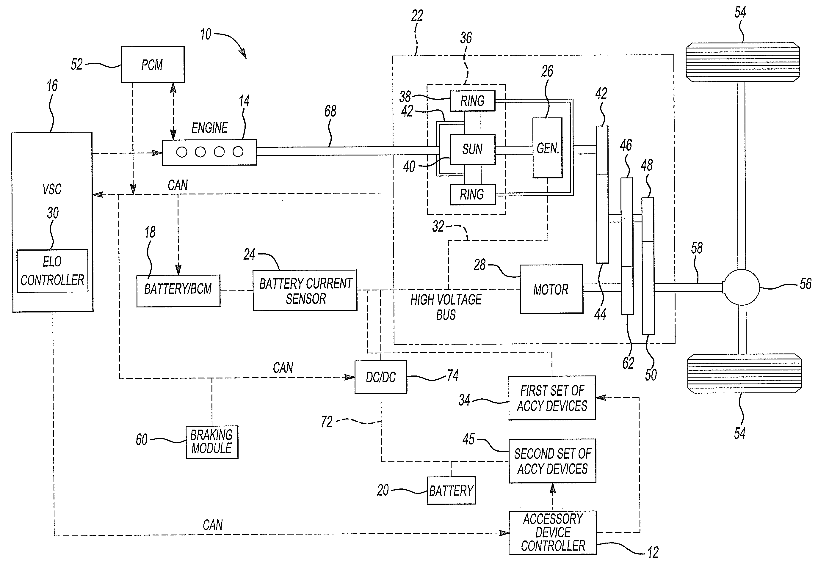
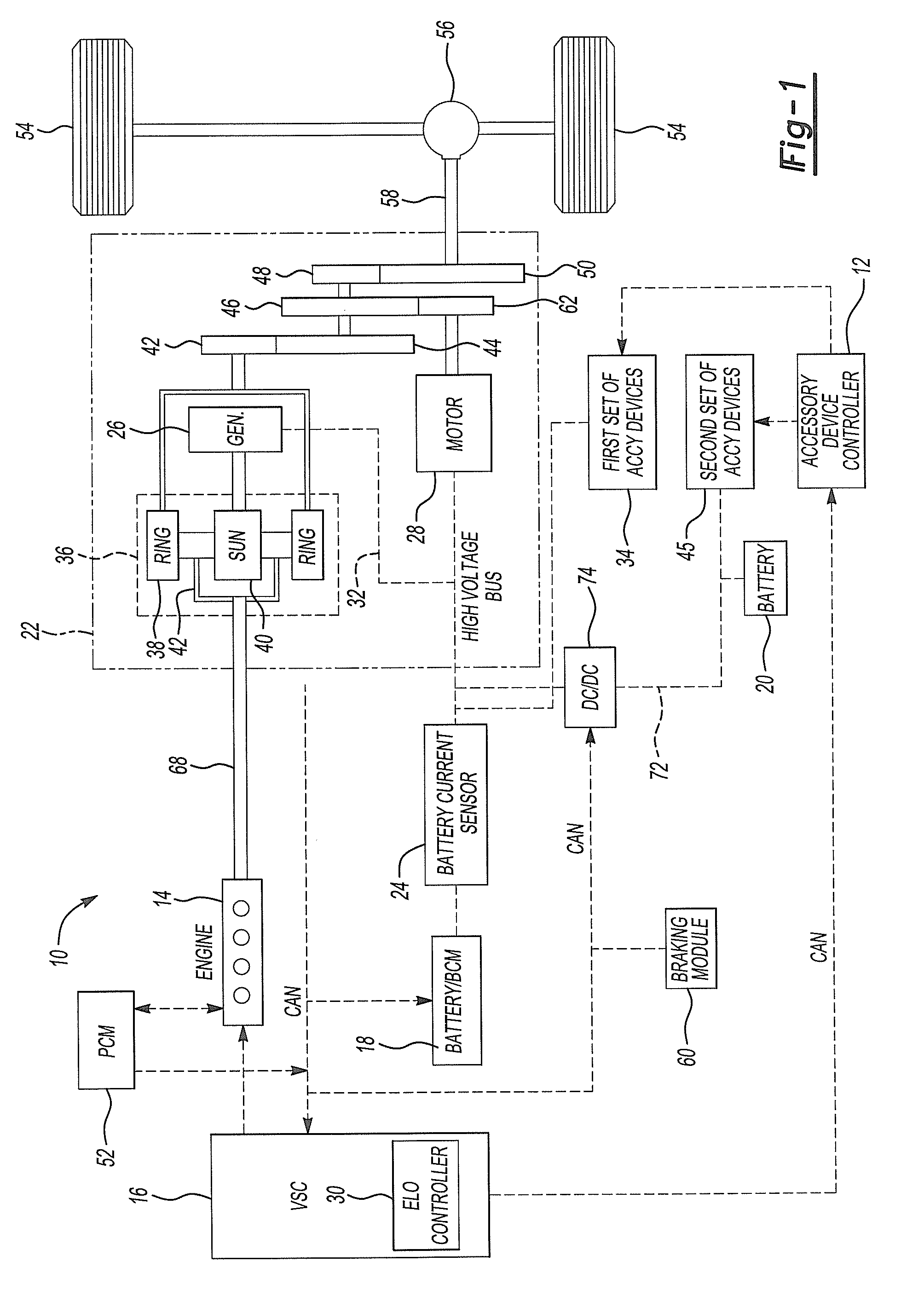
[0018]Referring to FIG. 1, a hybrid vehicle system 10 is shown in accordance to one embodiment of the present invention. In general, the system 10 may be related to a parallel-series hybrid vehicle (PSHEV) system, a series hybrid electric vehicle (SHEV), a parallel hybrid electric vehicle (PHEV), and a fuel cell hybrid vehicle (FCHEV). The system 10 includes a gasoline-fueled internal combustion engine (ICE) 14, a vehicle system controller (VSC) 16, a high voltage battery 18, and a low voltage battery 20.

[0019]The internal combustion engine 14 and high voltage battery 18 are coupled to the vehicle driveline through an power transmission unit 22 having a first motor / generator 26 and a second motor / generator 28. The first motor / generator 26 functions primarily as a generator and the second motor / generator 28 functions primarily as a motor. The high voltage battery 18 is configured to store electrical energy produced by the first motor / generator 26 or the second motor / generator 28. A ...


PUM


Abstract

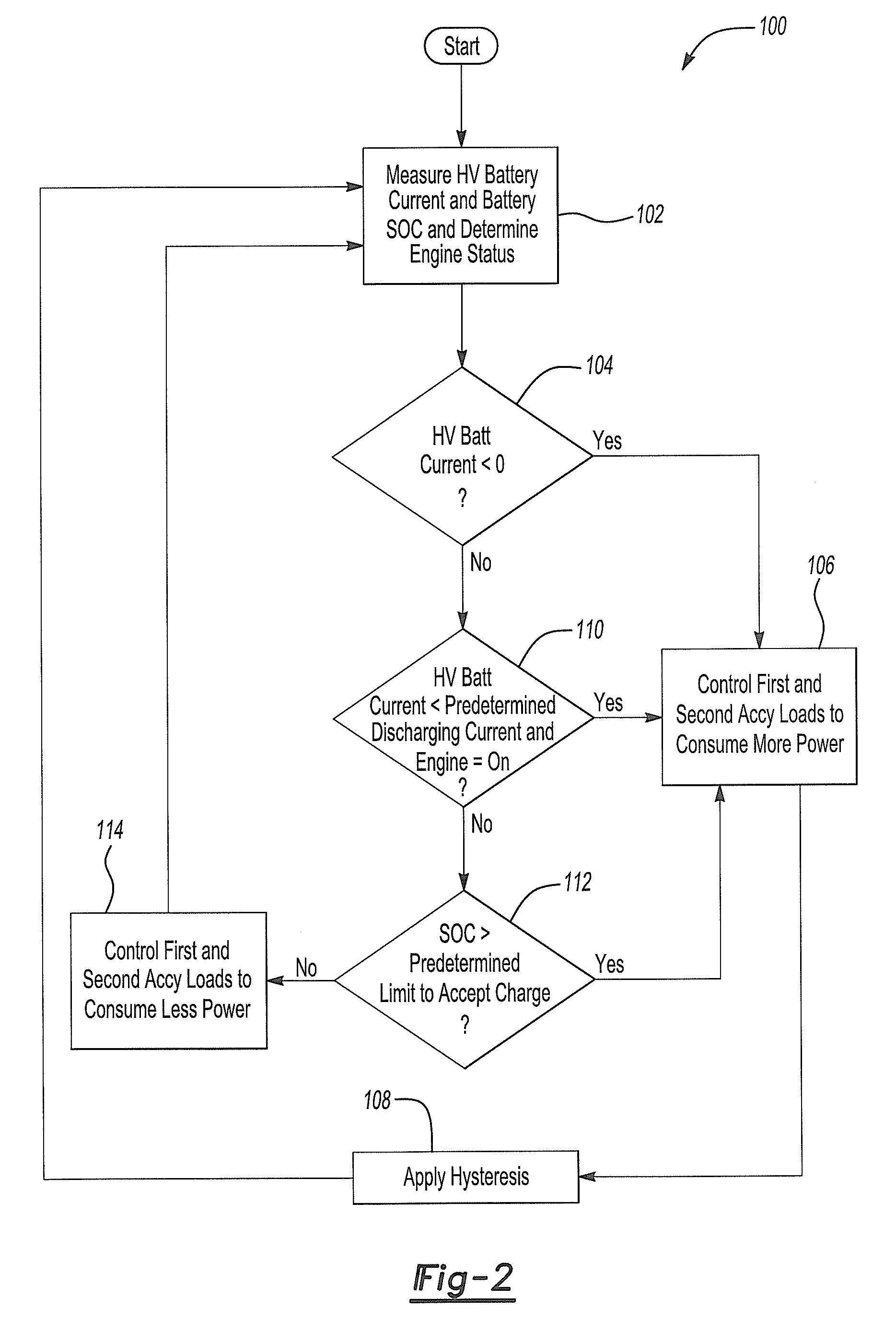
A system and method for controlling the electrical power consumption of an accessory device. A power transmission unit is adapted to generate electrical power. The system comprises a first controller, a current sensor and a second controller. The first controller is adapted to control the operation of the accessory device. The current sensor is configured to measure an amount of current being charged and discharged to and from the battery and generate a signal that corresponds to the measured amount of current charged and discharged to and from the battery. The second controller is configured to receive the signal from the current sensor and generate flag signal in response to detecting that current is being charged to the battery. The first controller is further adapted to control the accessory device to consume increased power from the electrical power generated by the power transmission unit in response to the flag signal.

Description

BACKGROUND OF THE INVENTION[0001]1. Field of the Invention[0002]Embodiments of the present invention generally relate to electrical load control of accessories in a vehicle.[0003]2. Background Art[0004]Keeping power losses to a minimum helps to increase fuel economy for vehicles. It is generally well known that vehicle electrical accessory devices (or loads) use a significant amount of power and that keeping power losses associated with vehicle electrical accessory usage to a minimum may increase fuel economy for a vehicle. Hybrid electric vehicles utilize a high voltage battery a fuel power engine, and regenerative braking for sources of power. Each of these sources may or may not be actively outputting power during various operating modes of the HEV. During periods of high wheel torque demand, the engine and battery may both be providing power to the wheels to meet high wheel torque demand. Any electrical accessory device that are on must continue to be powered during moments of h...

Claims


Application Information

Patent Timeline
IPC IPC(8): H02J7/00
CPCB60K1/02Y02T10/6239B60K6/445B60K6/547B60W10/08B60W10/26B60W10/30B60W20/00B60W2510/244H02J1/14H02J7/1423H02J7/1438H02J7/1461Y02T10/7005Y02T10/92B60K6/365Y02T10/62Y02T10/70H02J7/0048B60W2710/28B60W20/15B60W10/28
Inventor MACK, DAVID
Owner FORD GLOBAL TECH LLC
Learn More