Thermal pillow

a pillow and thermal insulation technology, applied in the field of electronic components, can solve the problems of stress management deficiencies, premature device failure, premature device failure, manufacturing complexity, etc., and achieve the effect of improving the heat dissipation of electronic components

Active Publication Date: 2008-09-18
GLOBALFOUNDRIES US INC
View PDF21 Cites 35 Cited by
  • Summary
  • Abstract
  • Description
  • Claims
  • Application Information

AI Technical Summary

Benefits of technology

[0011]Bearing in mind the problems and deficiencies of the prior art, it is therefore an object of the present inventi...

Problems solved by technology

However, each of these known devices brings with it the issues of stress management deficiencies, manufacturing complexity, reliability concerns and/, or high costs.
Any stress management deficiencies can lead to premature device failure.
However, since flexibility remains important to the mounting design to ensure constant contact while under vibration and shock induced forces, rigid configurations are often un...

Method used


Image

  • Thermal pillow
  • Thermal pillow
  • Thermal pillow

Examples


Embodiment Construction

)

[0030]In describing the preferred embodiment of the present invention, reference will be made herein to FIGS. 1A-5E of the drawings in which like numerals refer to like features of the invention.

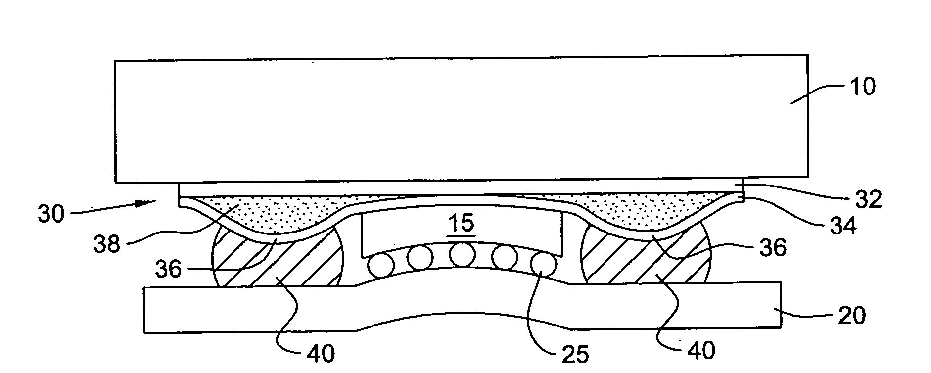
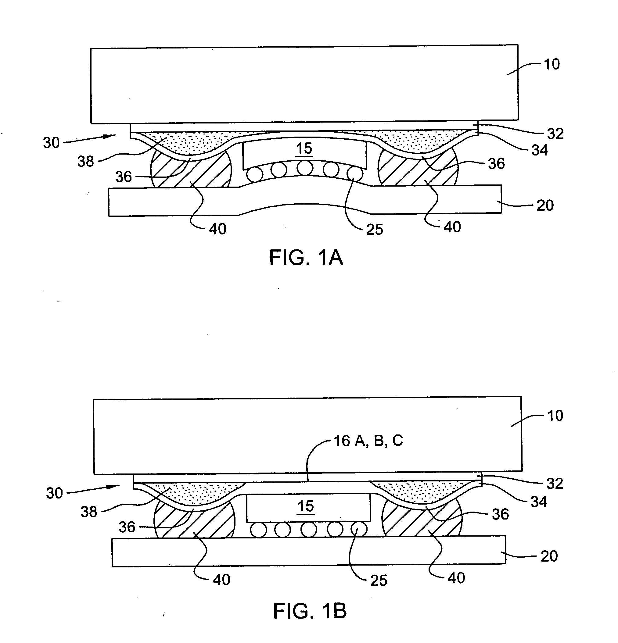
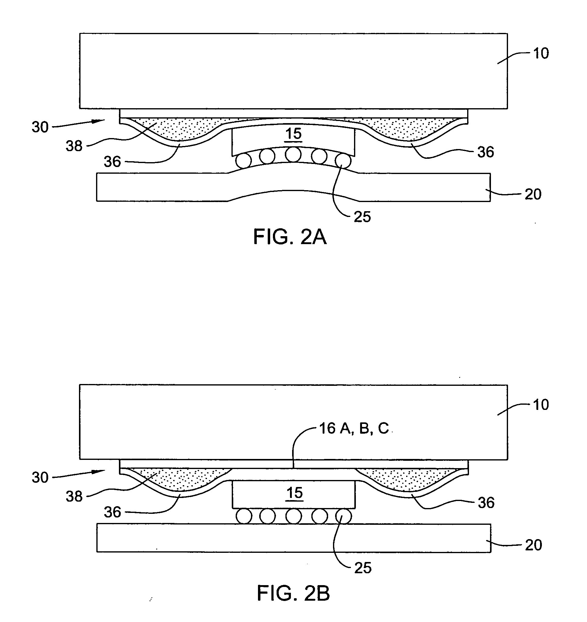
[0031]Broadly stated, this invention comprises a thermal pillow assembly for enhancing and improving heat dissipation from an electronic module, such as, an integrated circuit (“IC”) device while minimizing stresses, thermal mismatches, and costs. For convenience, the following description will be directed to semiconductors and IC's, however, it will be appreciated by those skilled in the art that the invention can be used for any type of electronic component.

[0032]Referring to the drawings, a heat sink (or thermally conducting lid) 10 is shown attached to an integrated circuit chip 15 via the thermal pillow assembly of the present invention. At an opposite side, the chip 15 is attached to a module or printed circuit board 20 using solder balls 25. The thermal pillow assembly of the inventi...


PUM


Abstract

Methods, apparatus and assemblies for enhancing heat transfer in electronic components using a flexible thermal pillow. The flexible thermal pillow has a thermally conductive material sealed between top and bottom conductive layers, with the bottom layer having a flexible reservoir residing on opposing sides of a central portion of the pillow that has a gap. The pillow may have roughened internal surfaces to increase an internal surface area within the pillow for enhanced heat dissipation. In an electronic assembly, the central portion of the pillow resides between a heat sink and heat-generating component for the thermal coupling there-between. During thermal cycling, the flexible reservoir of the pillow expands to retain thermally conductive material extruded from the gap, and then contracts to force such extruded material back into the gap. An external pressure source may contact the pillow for further forcing the extruded thermally conductive material back into the gap.

Description

BACKGROUND OF THE INVENTION[0001]1. Field of the Invention[0002]The present invention relates to electronic components, and in particular, to methods and thermal assemblies for enhancing heat dissipation from electronic components.[0003]2. Description of Related Art[0004]Modern electronic modules include microchips and other circuit components mounted on printed circuit boards. Over the years, the speeds and power requirements of these modules have rapidly increased while the sizes thereof have shrunk. Overall, this has lead to a significant increase in power density.[0005]During normal operating conditions, these modules generate heat or thermal energy from the microchips and other components. While some low power electronic components are able to dissipate this generated heat directly into the ambient, most require assistance to dissipate any heat that is generated during normal operating conditions.[0006]Cooling plates or heat sinks are often used to assist high power electronic ...

Claims


Application Information

Patent Timeline
IPC IPC(8): H05K7/20
CPCH01L23/42H01L23/433H01L2224/16H01L2224/73253H01L2924/01004H01L2924/3511H01L2924/01079H01L2924/16152H01L2924/00014H01L2924/00011H01L2224/0401
Inventor BRODSKY, WILLIAM L.BROFMAN, PETER J.BUSBY, JAMES A.CHAMBERLIN, BRUCE J.CUMMINGS, SCOTT A.EDWARDS, DAVID L.FLEISCHMAN, THOMAS J.GRIFFIN, MICHAEL J.IRUVANTI, SUSHUMNALONG, DAVID C.MUNCY, JENNIFER V.SUSKO, ROBIN A.
Owner GLOBALFOUNDRIES US INC
Why Eureka
Try Eureka