High speed multi-modulus prescalar divider

a multi-modulus, prescalar technology, applied in the field of electronic circuitry, can solve the problems of not being able to conveniently generate every required frequency, the pulse-swallowing technique may generate undesirable harmonic frequency components, etc., and achieve the effect of high-speed input signals, low power consumption, and no glitches

Active Publication Date: 2008-09-18
MACOM CONNECTIVITY SOLUTIONS LLC
View PDF10 Cites 21 Cited by
  • Summary
  • Abstract
  • Description
  • Claims
  • Application Information

AI Technical Summary

Benefits of technology

[0007]The multi-modulus divider is presented that divides a signal using division ratios such as 0.75, 0.875, 1, 1.125, and 1.25, dynamically in response to a control signal, by selecting between different phases of a reference frequency. The divider is able to divide high sp...

Problems solved by technology

However, the pulse-swallowing technique may generate undesirable harmonic frequencies components.
Further, i...

Method used


Image

  • High speed multi-modulus prescalar divider
  • High speed multi-modulus prescalar divider
  • High speed multi-modulus prescalar divider

Examples


Embodiment Construction

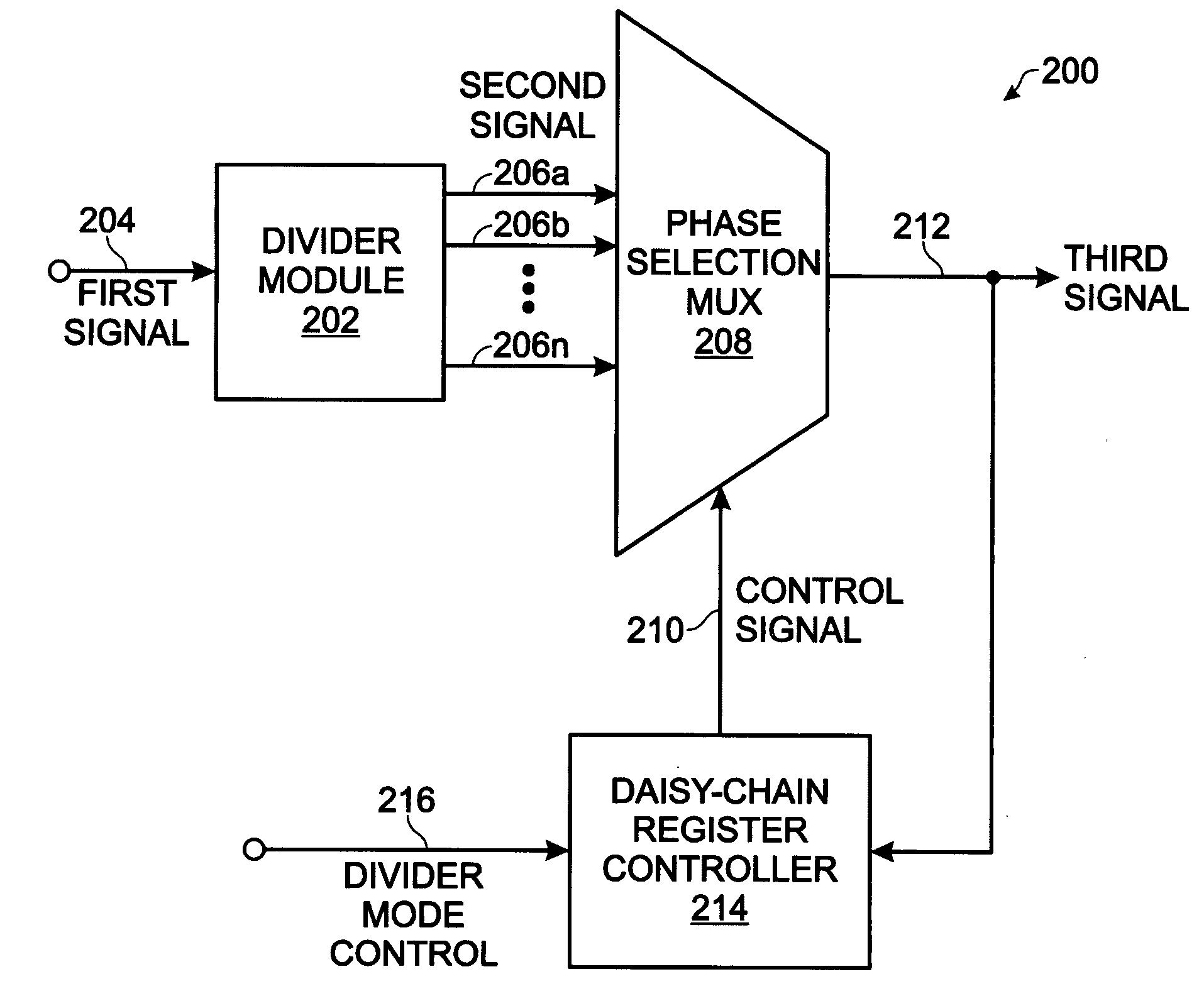
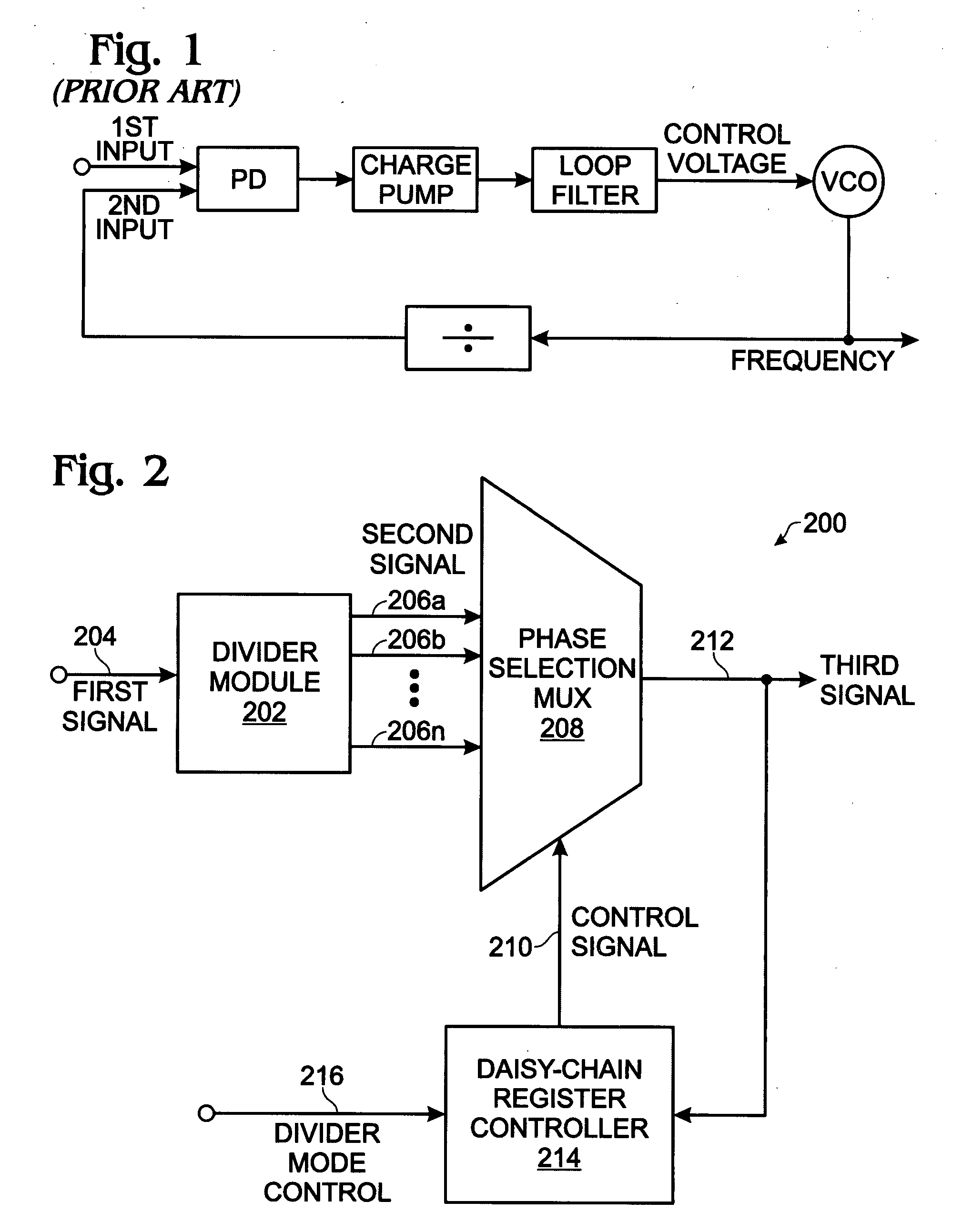
[0026]FIG. 2 is a schematic block diagram of a system for multi-modulus division. The system 200 comprises a divider module 202 having an input on line 204 to accept a first signal having a first frequency. Referencing FIG. 1 briefly, line 204 may be a VCO output for example. The divider module 202 divides the first frequency by an integral number and supplies a second signal with a plurality of phase outputs on line 206, each having a second frequency. Phase output lines 206a through 206n are shown, where n is not limited to any particular number.

[0027]A phase selection multiplexer (MUX) 208 has an input on lines 206 to accept the plurality of second signal phase outputs, and an input on line 210 to accept a control signal. The phase selection multiplexer 208 has an output on line 212 to supply a second signal phase selected in response to the control signal on line 210. A daisy-chain register controller 214 has an output on line 210 to supply the control signal for dynamically sel...


PUM


Abstract

A system and method are provided for multi-modulus division. The method accepts an input first signal having a first frequency and divides the first frequency by an integral number. A second signal is generated with a plurality of phase outputs, each having a second frequency. Using a daisy-chain register controller, phase outputs are selected and supplied as a third signal with a frequency. Selecting phase outputs using the daisy-chain register controller includes supplying the third signal as a clock signal to registers having outputs connected in a daisy-chain. Then, a sequence of register output pulses is generated in response to the clock signals, and register output pulses are chosen from the sequence to select second signal phase outputs. By using 8-second signal phase outputs, a third signal is obtained with a frequency equal to the second frequency multiplied by one of the following numbers: 0.75, 0.875, 1, 1.125, or 1.25.

Description

BACKGROUND OF THE INVENTION[0001]1. Field of the Invention[0002]This invention generally relates to electronic circuitry and, more particularly, to a system and method for multi-modulus prescalar division.[0003]2. Description of the Related Art[0004]FIG. 1 is a schematic block diagram of a conventional phase locked loop (prior art). A phase detector (or frequency detector) receives a first input signal, such as might be supplied on a serial data stream or a clock source, and compares it to a second input signal supplied by the divider. The phase detector (PD) generates an output that is responsive to difference in timing between the two input signals. A charge-pump may be added to improve the response of the PLL, as the phase detector output does not necessarily have enough drive to instantaneously charge (or discharge) the loop filter reactances. The loop filter is typically a low-pass filter, and is used to control the overall loop response. The voltage controlled oscillator (VCO)...

Claims


Application Information

Patent Timeline
IPC IPC(8): H04L27/00
CPCG06F7/68H03L7/193H03K23/68
Inventor AN, HONGMINGPANG, SIMONDO, VIET LINH
Owner MACOM CONNECTIVITY SOLUTIONS LLC
Why Eureka
Try Eureka