Electrophotographic photoconductor, electrophotographic process cartridge containing the same and electrophotographic apparatus containing the same

a photoconductor and electrophotography technology, applied in the direction of electrographic process equipment, instruments, corona discharge, etc., can solve the problem of temporary loss of low friction of a photoconductor, and achieve the effect of superior cleanability and low increase in friction coefficient and wear

Inactive Publication Date: 2008-09-18
RICOH KK
View PDF22 Cites 28 Cited by
  • Summary
  • Abstract
  • Description
  • Claims
  • Application Information

AI Technical Summary

Benefits of technology

[0037]An object of the present invention is to provide an electrophotographic photoconductor having an extremely low increase in friction coefficient and wear while also having superior cleanability even after long-term or large-volume printing. In addition, an object of the present invention is to provide an electrophotographic apparatus for forming an image using a polymerization toner without providing a unit for externally supplying a lubricant to a photoconductor.
[0038]In order to solve the conventional problems, the inventors of the present invention found that loss of lubricant due to bleedout can be prevented in advance by selecting a three-dimensionally crosslinked film for the material of the a photoconductor surface layer which forms a film by radial polymerization of trimethylolpropane triacrylate having a high crosslink density, selecting dimethylpolysiloxane which is one of silicone oil having a superior effect of reducing friction coefficient from among various lubricants, and then chemically bonding the dimethylpolysiloxane to a three-dimensionally crosslinked resin matrix of the material of the photoconductor surface layer.
[0039]Generally, the low friction of a photoconductor is temporarily lost in a charging step of an electrophotographic process. With regard to this phenomenon, it was found that the loss of low friction can be avoided by dispersing a second component of a lubricant in the form of unreactive lubricating fine particles. In the case of only using the unreactive lubricating fine particles alone, a large amount of the unreactive lubricating fine particles are necessarily contained to maintain the low friction of a photoconductor. While a chemically-bonding dimethylpolysiloxane is used with lubricating fine particles, a large amount of the lubricating fine particles are not needed. Consequently, deterioration of film strength caused by containing a large amount of lubricant can be suppressed.

Problems solved by technology

Generally, the low friction of a photoconductor is temporarily lost in a charging step of an electrophotographic process.

Method used


Image

  • Electrophotographic photoconductor, electrophotographic process cartridge containing the same and electrophotographic apparatus containing the same
  • Electrophotographic photoconductor, electrophotographic process cartridge containing the same and electrophotographic apparatus containing the same
  • Electrophotographic photoconductor, electrophotographic process cartridge containing the same and electrophotographic apparatus containing the same

Examples


example 1

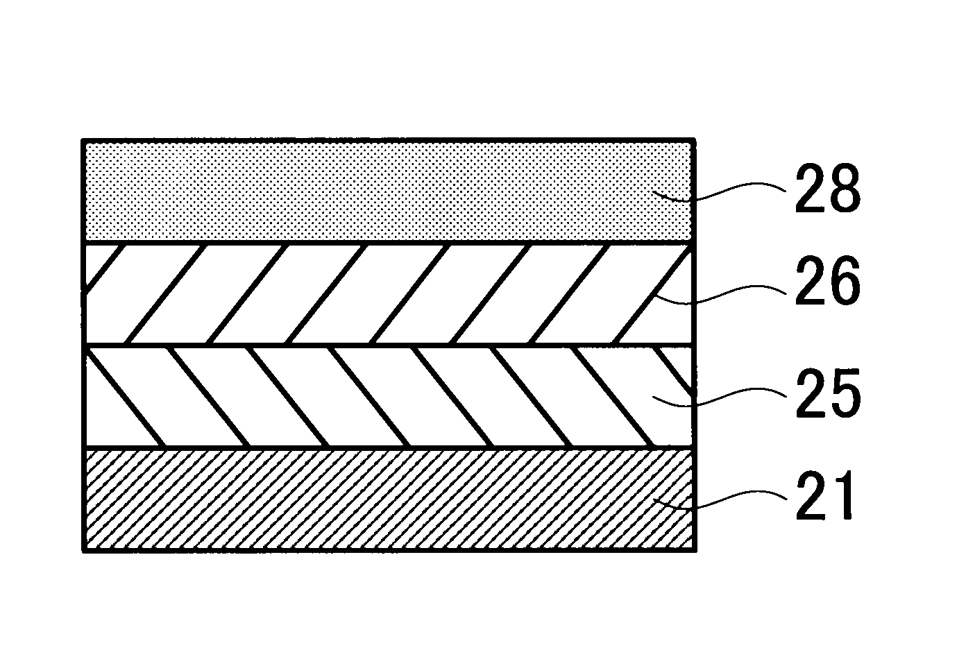
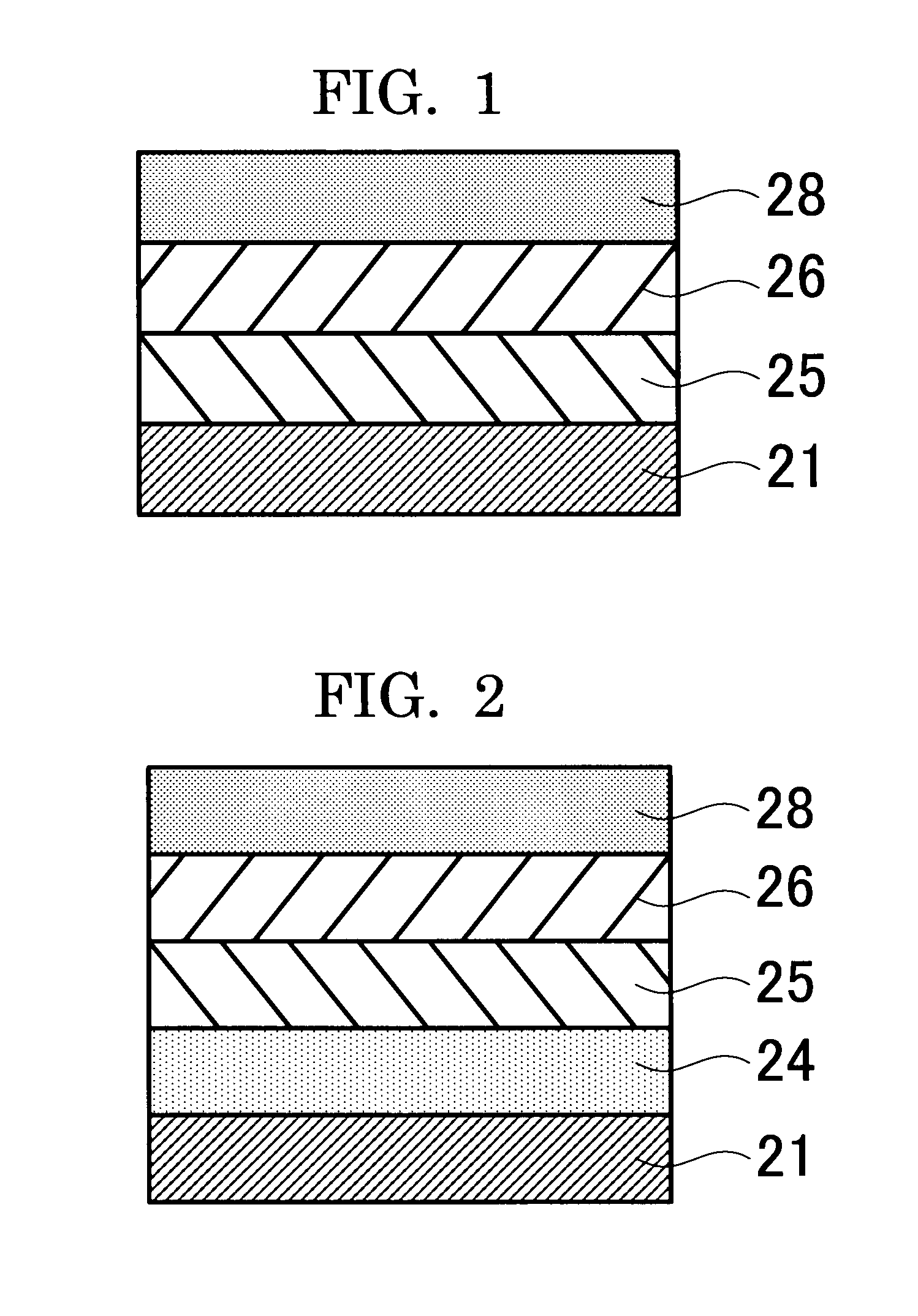
[0172]A coating liquid for undercoat layer, coating liquid for charge generating layer and coating liquid for charge transporting layer having the compositions indicated below were sequentially coated and dried on an aluminum drum having a wall thickness of 0.8 mm, length of 340 mm and outer diameter of 30 mm to form a 3.5 μm-thick undercoat layer, 0.2 μm-thick charge generating layer and 19 μm-thick charge transporting layer. After spray coating a coating liquid for crosslinkable resin surface layer having the composition indicated below thereon, the drum was placed at a distance of 120 mm from a UV curing lamp followed by carrying out UV curing while rotating the drum. The luminosity of the UV curing lamp at this position was 600 mW / cm2 (measured value obtained with the UIT-150 integrating ultraviolet photometer by Ushio Inc.). In addition, the drum rotating speed was 25 rpm. During UV curing, a rod-shaped metal block was contained inside the aluminum drum. In addition, UV curing ...

example 2

[0177]An electrophotographic photoconductor was produced in the same manner as in Example 1 with the exception of changing the amount of the methacryloyl-modified dimethylpolysiloxane having radically polymerizable functional groups on both ends thereof (X-22-164C, Shin-Etsu Chemical Co., Ltd.) of the crosslinkable resin surface layer of Example 1 from 13.0 parts by mass to 2.0 parts by mass, and changing the amount of the acrylic-silicone copolymer (Chaline R-170S, Nisshin Chemical Industry Co., Ltd.) from 13.0 parts by mass to 4.0 parts by mass.

example 3

[0178]An electrophotographic photoconductor was produced in the same manner as in Example 1 with the exception of changing the amount of the methacryloyl-modified dimethylpolysiloxane having radically polymerizable functional groups on both ends thereof (X-22-164C, Shin-Etsu Chemical Co., Ltd.) of the crosslinkable resin surface layer of Example 1 from 13.0 parts by mass to 7.0 parts by mass, and changing the amount of the acrylic-silicone copolymer (Chaline R-170S, Nisshin Chemical Industry Co., Ltd.) from 13.0 parts by mass to 7.0 parts by mass.


PUM

PropertyMeasurementUnit
particle size distributionaaaaaaaaaa
friction coefficientaaaaaaaaaa

Abstract

An object of the present invention is to provide an electrophotographic photoconductor having an extremely low increase in friction coefficient and wear, while also having superior cleanability even after long-term or large-volume printing, and to provide an electrophotographic apparatus for forming an image using a polymerization toner without providing a unit for externally supplying a lubricant to a photoconductor. Namely, the present invention provides an electrophotographic photoconductor having a photosensitive layer and a crosslinked resin surface layer over a conductive substrate, wherein the crosslinked resin surface layer at least contains trimethylolpropane triacrylate, a dimethylpolysiloxane having a radically polymerizable functional group, and lubricating fine particles.

Description

BACKGROUND OF THE INVENTION[0001]1. Field of the Invention[0002]The present invention relates to an electrophotographic apparatus and an electrophotographic cartridge. The electrophotographic apparatus and the electrophotographic cartridge of the present invention are applied to a photocopier, facsimile machine, laser printer or direct digital platesetter and the like.[0003]2. Description of the Related Art[0004]Although the electrophotographic photoconductors used in electrophotographic apparatuses applied to photocopiers, laser printers and the like formerly consisted primarily of inorganic photoconductors such as selenium, zinc oxide and cadmium sulfate, organic photoconductors (OPC), which are more advantageous than inorganic photoconductors in terms of reducing the burden on the global environment, reducing costs and allowing greater freedom of design, are currently used at a rate that is rapidly approaching 100% of the total production volume of electrophotographic photoconduc...

Claims


Application Information

Patent Timeline
Patent Type & Authority Applications(United States)
IPC IPC(8): G03G15/04
CPCG03G5/0546G03G5/0578G03G5/0592G03G5/0614G03G2215/00957G03G5/14734G03G5/14743G03G5/14786G03G5/14791G03G5/071G03G5/072
Inventor KAMI, HIDETOSHISUZUKI, TETSUROTAMURA, HIROSHIIKUNO, HIROSHIFUJIWARA, YUKIOIWAMOTO, TAKAFUMI
Owner RICOH KK
Why Eureka
Try Eureka