Double-side polishing apparatus

a polishing apparatus and double-side technology, applied in the direction of grinding machine components, manufacturing tools, lapping machines, etc., can solve the problems of above-described conventional technologies, which have the following problems, and take a long time, so as to achieve accurate measurement, accurate polishing, and correct thickness

Active Publication Date: 2008-09-18
FUJIKOSHI MACHINERY
View PDF12 Cites 17 Cited by
  • Summary
  • Abstract
  • Description
  • Claims
  • Application Information

AI Technical Summary

Benefits of technology

[0025]In the double-side polishing apparatus of the present invention, the thickness of the wafer can be measured while polishing the wafer, and the wafer can be accurately polished to have the correct thickness. Since a coherent laser beam is used as a measuring light, the thickness measuring equipment can be provided to the frame separated from the upper polishing plate, so that the thickness can be accurately measured without being badly influenced by rotation, vibration, etc. of the upper polishing plate. Further, there are few spatial obstructions in a space above the upper polishing plate, so that the window section can be optionally formed in the upper polishing plate.
[0026]Therefore, the thickness of the center part of the wafer too can be measured, so that the thickness of the wafer can be reliably measured.

Problems solved by technology

This problem can be solved by calculating the polishing rate of a sample wafer for each batch, but it takes a long time and it is inefficient.
However, the above described conventional technologies have following problems.

Method used


Image

  • Double-side polishing apparatus
  • Double-side polishing apparatus
  • Double-side polishing apparatus

Examples


Embodiment Construction

[0033]Preferred embodiments of the present invention will now be described in detail with reference to the accompanying drawings.

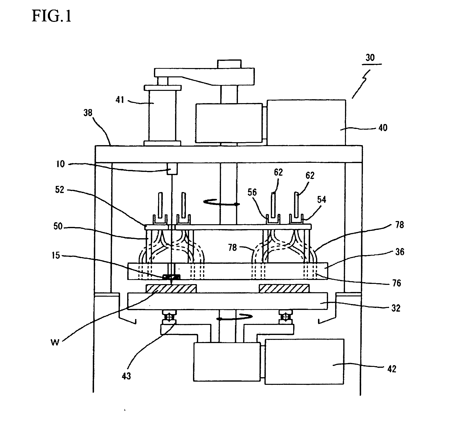
[0034]FIG. 1 is a front explanation view of an embodiment of a double-side polishing apparatus 30 of the present invention.

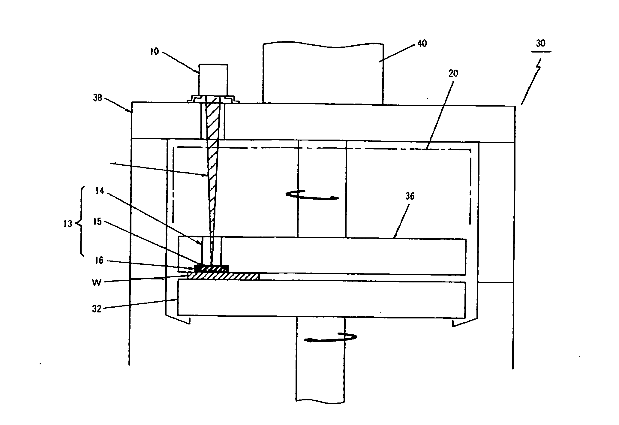
[0035]The double-side polishing apparatus 30 has: a lower polishing plate 32, whose upper face is a polishing face; and an upper polishing plate 36, whose lower face is a polishing face and which is provided above the lower polishing plate 32 and capable of moving upward and downward.

[0036]The polishing plates 32 and 36 are rotated, in the opposite directions, by plate driving units 40 and 42. The upper polishing plate 36 is rotated about its own axis by the driving unit 40, e.g., motor, which is provided to a frame 38. The upper polishing plate 36 is moved upward and downward by a vertical driving mechanism, e.g., a cylinder unit 41.

[0037]The lower polishing plate 32 is rotated about its own axis by the driving unit 42, e.g., motor. A...


PUM


Abstract

The double-side polishing apparatus for polishing both faces of a wafer is capable of reliably measuring not only a thickness of an outer part of the wafer but also a thickness of a center part thereof. The double-side polishing apparatus comprises: a lower polishing plate; an upper polishing plate held by a frame; and a carrier having a through-hole for holding the wafer. A window section, through which a laser beam passes, is formed in a part of the upper polishing plate, under which the wafer held by the carrier passes. An optical thickness measuring equipment is provided to a part of the frame, under which the window section passes while the upper polishing plate is rotated. The thickness measuring equipment emits the laser beam through the window section, receives reflected beams reflected from an upper face and a lower face of the wafer, and calculates the thickness of the wafer on the basis of peak values of the reflected beams.

Description

BACKGROUND OF THE INVENTION[0001]The present invention relates to a double-side polishing apparatus, more precisely relates to a double-side polishing apparatus capable of measuring a thickness of a wafer while polishing the wafer.[0002]A conventional double-side polishing apparatus for polishing both faces of a wafer comprises: a lower polishing plate whose upper face acts as a polishing face; an upper polishing plate whose lower face acts as a polishing face; a frame holding the upper polishing plate above the lower polishing plate, the frame vertically moving the upper polishing plate; a carrier being provided between the lower polishing plate and the upper polishing plate, the carrier having a through-hole, in which the wafer is held; a plate driving unit for rotating the lower polishing plate and the upper polishing plate about their axes; a carrier driving unit for rotating the carrier; and a slurry supply unit. The lower polishing plate, the upper polishing plate and the carr...

Claims


Application Information

Patent Timeline
Patent Type & Authority Applications(United States)
IPC IPC(8): B24B7/00B24B37/013B24B37/08B24B49/12H01L21/304
CPCB24B37/013B24B49/12B24B37/205B24B37/08
Inventor ONISHI, SUSUMUMARUTA, MASASHI
Owner FUJIKOSHI MACHINERY
Why Eureka
Try Eureka