Method and Apparatus for Monitoring the Restriction Level of a Vehicular Air Filter Element

a technology of air filter element and restriction level, which is applied in the direction of combustion-air/fuel-air treatment, instruments, separation processes, etc., can solve the problems of airflow through the element becoming impeded or restricted, airflow therethrough, and considerable downstream pressure drop

Active Publication Date: 2008-09-25
GM GLOBAL TECH OPERATIONS LLC
View PDF9 Cites 34 Cited by
  • Summary
  • Abstract
  • Description
  • Claims
  • Application Information

AI Technical Summary

Problems solved by technology

As it continues to trap particulate matter, the air filter element slowly saturates with debris, and airflow through the element becomes impeded or restricted.
When the air filter element becomes fully saturated (or dirty), airflow therethrough is substantially restricted and a considerable decrease in downstream pressure results.
When employed in a vehicular air induction system, a fully saturated filter element may negatively impact the performance of the internal combustion engine.
For example, a restricted filter element may lead to diminished horsepower and fuel efficiency.
Unfortunately, it is often cumbersome to determine if an air filter element requires replacement.
A visual inspection may be performed, but is typically inconvenient, inaccurate for determin

Method used


Image

  • Method and Apparatus for Monitoring the Restriction Level of a Vehicular Air Filter Element
  • Method and Apparatus for Monitoring the Restriction Level of a Vehicular Air Filter Element
  • Method and Apparatus for Monitoring the Restriction Level of a Vehicular Air Filter Element

Examples


Embodiment Construction

[0014]The following detailed description is merely exemplary in nature and is not intended to limit the invention or the application and uses of the invention. Furthermore, there is no intention to be bound by any expressed or implied theory presented in the preceding technical field, background, brief summary, or the following detailed description.

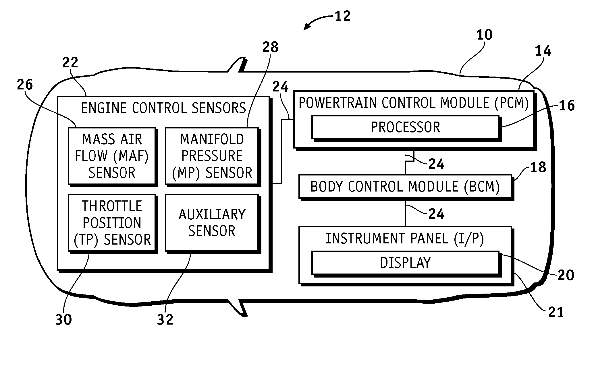
[0015]FIG. 1 is a functional view of a vehicle 10 including an onboard filter restriction monitoring system 12 suitable for performing an embodiment of the inventive air filter monitoring method. Filter restriction monitoring system 12 suitably includes a powertrain control module (PCM) 14 including a powertrain processor 16, a body control module (BCM) 18, an instrument panel (I / P) 21 including a display 20, and a number of engine control sensors 22. PCM 14, BCM 18, I / P 21 and engine control sensors 22 are electrically coupled by way of communication lines 24, which may include, for example, one or more serial or parallel data buses. Col...


PUM

PropertyMeasurementUnit
Pressureaaaaaaaaaa
Speedaaaaaaaaaa
Mass flow rateaaaaaaaaaa

Abstract

A process is provided for monitoring the filter restriction level of a filter element. The filter element is utilized by an air induction system deployed on a vehicle that includes a mass air flow sensor, a manifold pressure sensor, and a throttle position sensor. The process includes receiving (i) throttle position from the throttle position sensor, (ii) mass flow rate from the mass air flow sensor, and (iii) manifold pressure from the manifold pressure sensor. A reference pressure is determined from the received mass flow rate and the received throttle position, a pressure differential is established between the reference pressure and the received manifold pressure, and a filter restriction level is identified from the established pressure differential and the received mass flow rate.

Description

TECHNICAL FIELD[0001]The present invention generally relates to a vehicular filter restriction monitoring system and, more particularly, to a method for monitoring the restriction level of an air filter element employed by a vehicular air induction system.BACKGROUND OF THE INVENTION[0002]Air filters are well-known devices that are positioned within an airflow path to remove particulate matter (e.g., dust, pollen, mold, bacteria, and other debris) therefrom. At least one air filter element is commonly employed in a vehicle's air induction system. The air filter element prevents particulate matter from traveling downstream through the intake manifold and into the combustion chambers of the vehicle's internal combustion engine. Vehicular filter elements are typically rectangular panels, but may also assume other shapes (e.g., annular or conical shapes). Due to their desirable filtration properties and low cost, disposable paper-based filter elements are commonly utilized; however, othe...

Claims


Application Information

Patent Timeline
IPC IPC(8): B01D46/30F02M35/10
CPCB01D46/0086B01D46/444B01D46/446F02M35/10386F02M35/024F02M35/09F02M35/1038B01D2279/60
Inventor BENSCOTER, SCOTT J.STAAT, LAWRENCE A.STENSON, DENNIS P.MC CORMICK, STEVEN J.VAN VECHTEN, ROGER G.
Owner GM GLOBAL TECH OPERATIONS LLC
Why Eureka
Try Eureka