Extended Leading-Edge Compressor Wheel

a compressor wheel and leading-edge technology, applied in the direction of machines/engines, liquid fuel engines, transportation and packaging, etc., can solve the problems of limited backward curvature, unstable airflow throughout the compressor, and the speed limit of the compressor impeller, so as to increase the energy transfer and pressure ratio, the effect of prolonging the flow

Inactive Publication Date: 2008-09-25
HONEYWELL INT INC
View PDF25 Cites 32 Cited by
  • Summary
  • Abstract
  • Description
  • Claims
  • Application Information

AI Technical Summary

Benefits of technology

[0008]The housing defines a shroud wall that forms an inlet leading into the compressor wheel. The compressor wheel includes a hub defining a hub wall connected to a hub edge of a plurality of blades (including main blades, and possibly including splitter blades). Each main blade defines a leading edge at an inlet end of the main blade, the leading edge extending from a hub-side at the hu

Problems solved by technology

Surging airflow occurs when a compressor operates at a relatively low flow rate with respect to the compressor pressure ratio, and the resulting flow of air throughout the compressor becomes unstable.
For turbocharged-engine applications there is a speed limit for compressor impellers due to mechanical stresses, low cycle fatigue, high cycle fatigue and vibration issues.
Moreover, in order to achieve desired pressure ratios, only a lim

Method used


Image

  • Extended Leading-Edge Compressor Wheel
  • Extended Leading-Edge Compressor Wheel
  • Extended Leading-Edge Compressor Wheel

Examples


Embodiment Construction

[0026]The invention summarized above and defined by the enumerated claims may be better understood by referring to the following detailed and description, which should be read with the accompanying drawings. This detailed description of particular preferred embodiments of the invention, set out below to enable one to build and use particular implementations of the invention, is not intended to limit the enumerated claims, but rather, it is intended to provide particular examples of them.

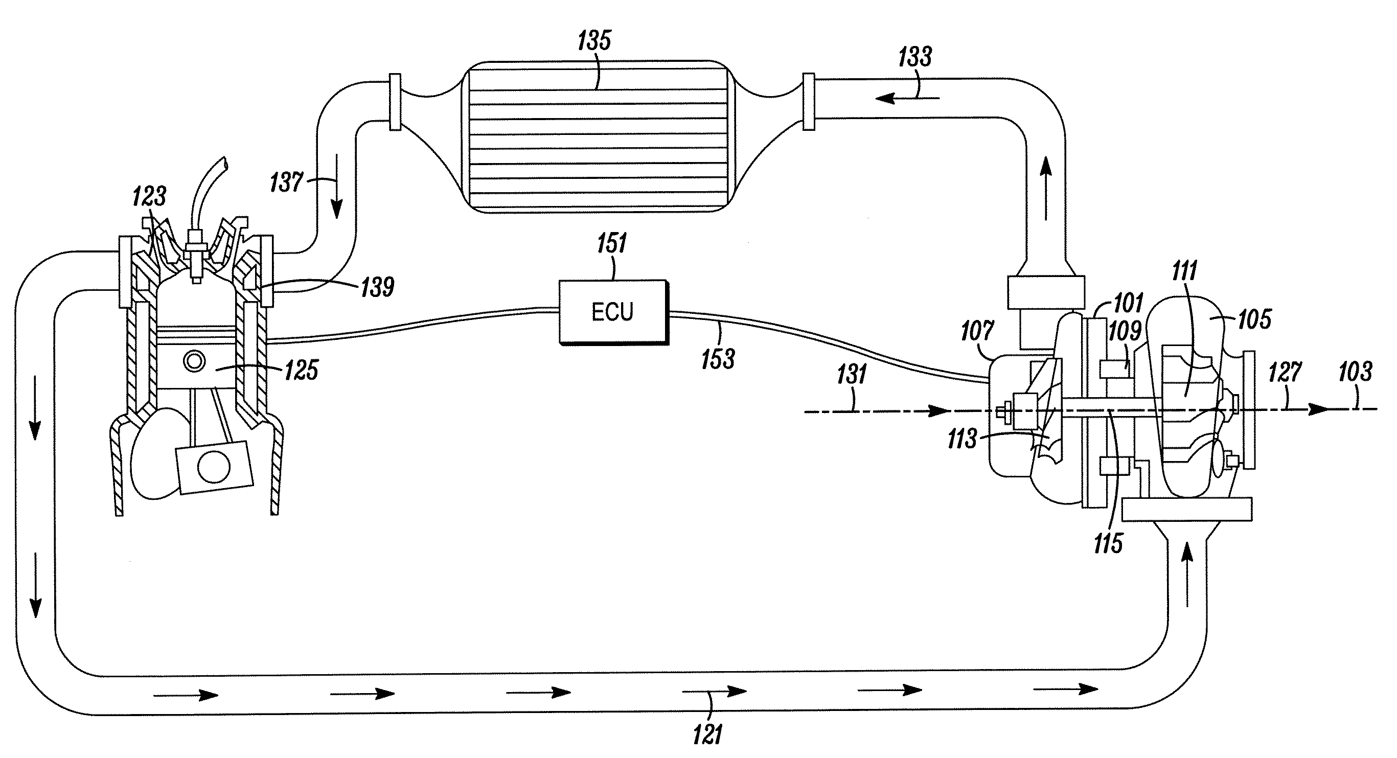
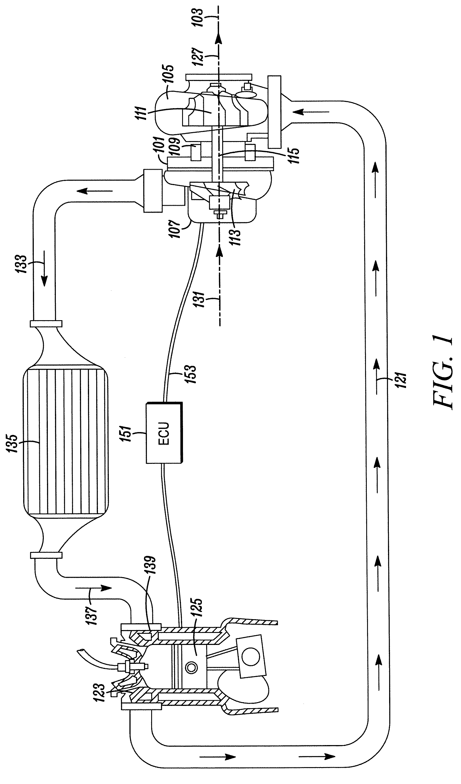
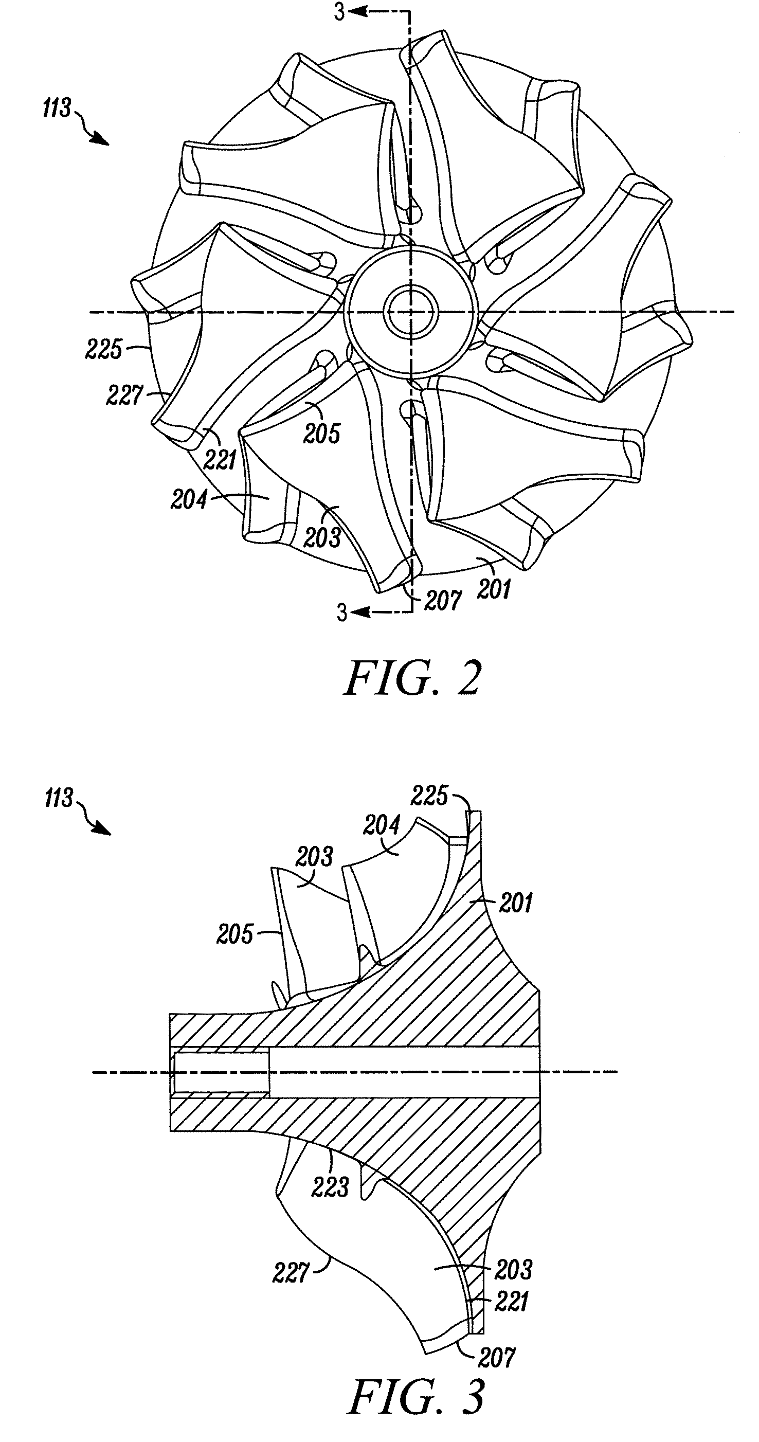
[0027]Typical embodiments of the present invention reside in a compressor wheel for a turbocharger, along with associated methods and apparatus (e.g., compressors, turbochargers and turbocharged internal combustion engines). Preferred embodiments of the invention are assemblies that provide for improved pressure ratios and / or related flow characteristics through the use of main blades (i.e., full compressor blades, as opposed to partial, splitter blades that extend downstream from a splitter blade le...


PUM


Abstract

A turbocharger system having a compressor housing containing a rotating compressor wheel with a plurality of main blades that define an impeller passageway from an inducer to an exducer. Each main blade has a leading edge characterized by an extension forming a non-planar, conical inducer leading edge, and a trailing edge characterized by a reverse-clip-extension forming a non-cylindrical, conical exducer trailing edge.

Description

[0001]The present invention relates generally to compressors for turbomachinery and, more particularly, to apparatus and methods of improving compressor performance.BACKGROUND OF THE INVENTION[0002]In turbocharger technology a rotating compressor wheel within a compressor housing sucks air through an intake duct, compresses it in an impeller passage, and diffuses it into a compressor housing. The compressed air is supplied to an intake manifold of an internal combustion engine. The operating range of a compressor extends from a surge condition (wherein the airflow is “surging”), occurring at low airflow rates, to a choke condition (wherein the airflow is “choked”) experienced at high airflow rates. Surging airflow occurs when a compressor operates at a relatively low flow rate with respect to the compressor pressure ratio, and the resulting flow of air throughout the compressor becomes unstable. “Choking” occurs when a compressor tries to operate at a high flow rate that exceeds the...

Claims


Application Information

Patent Timeline
IPC IPC(8): F02G5/00F01D5/00
CPCF04D29/30F04D29/284F05D2240/303
Inventor RENAUD, PHILIPPEDUBOIS, THOMASCHEN, HUA
Owner HONEYWELL INT INC
Why Eureka
Try Eureka