Combination of a Desalination Plant and a Salinity Gradient Power Reverse Electrodialysis Plant and Use Thereof

a technology of reverse electrodialysis and salinity gradient, which is applied in the direction of fluid pressure measurement, liquid/fluent solid measurement, peptide measurement, etc., can solve the problems of not being economically viable, not very efficient and economic in practice, and the pump consumption is too much energy for the salinity gradient power system to be economically viable, etc., to achieve a small salinity gradient power unit and higher power output

Active Publication Date: 2008-09-25
VLAAMSE INSTELLING VOOR TECHNOLOGISCH ONDERZOEK NV VITO
View PDF8 Cites 42 Cited by
  • Summary
  • Abstract
  • Description
  • Claims
  • Application Information

AI Technical Summary

Problems solved by technology

Such an indirect method of electricity production in a closed loop system therefore is considered here to be not very efficient and not economic in practice.
Most of the described installations are not viable due to installation (investment) costs and operational costs.
No convenient setup without the need for high-capacity pumps for bringing high salt solutions near river water or vice versa is proposed.
Such pumps consume too much energy for the salinity gradient power system to be economically viable.
In a lot of areas, access to river water is very difficult or even impossible near the sea.
These techniques require large amounts of energy in order to separate the salt from the seawater.
Thermal desalination technology (evaporation) is also very energy-demanding and consumes also important amounts of oil as a heat energy source.

Method used


Image

  • Combination of a Desalination Plant and a Salinity Gradient Power Reverse Electrodialysis Plant and Use Thereof
  • Combination of a Desalination Plant and a Salinity Gradient Power Reverse Electrodialysis Plant and Use Thereof

Examples


example

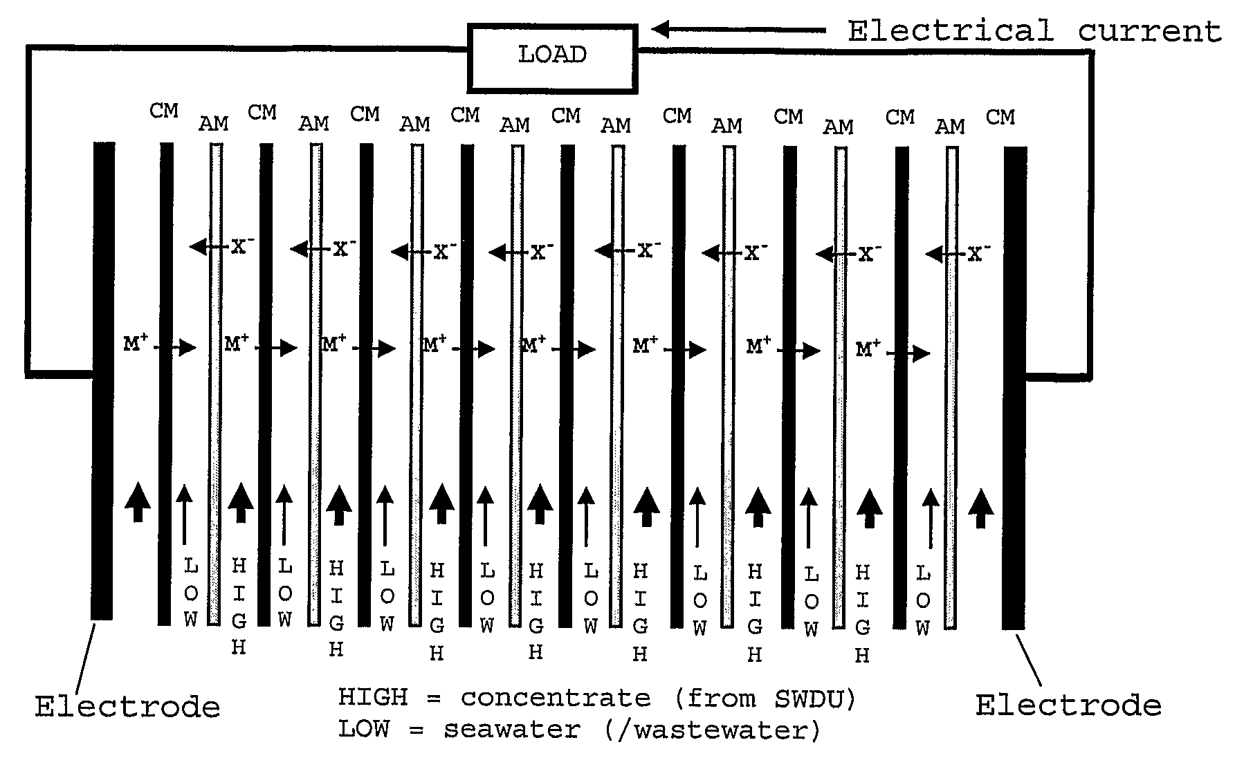
[0044]The SGP-RE unit consists of a set-up as used in electrodialysis (ED) but used in a reversed way. In such a set-up cation membranes (CM) and anion membranes (AM) are placed in an alternating sequence as indicated schematically in FIG. 1. Since the activity (concentration) of the salt ions in the SWDU concentrate (feed indicated as HIGH in the SGP-RE compartments) is much higher than the activity of the salt ions in the seawater (feed indicated as LOW in the SGP-RE compartments), there will be a diffusion of:[0045]cations from the SWDU concentrate (HIGH) compartments through the cation membranes into the seawater (LOW) compartments[0046]anions from the SWDU concentrate (HIGH) compartments through the anion membranes into the seawater (LOW) compartments

[0047]This diffusion of ions invokes an electrical voltage across the two SGP-RE electrodes and thus an electrical current through an electrical load. In FIG. 1 the electrode activity is not indicated. As with ED, the electrode ele...


PUM

PropertyMeasurementUnit
osmotic pressureaaaaaaaaaa
heightaaaaaaaaaa
pressureaaaaaaaaaa

Abstract

A desalination plant, includes a sea water intake, a desalination unit having a reverse osmosis or a thermal desalination unit, a fresh water outlet and a brine outlet. The plant also includes a salinity gradient power unit having a brine inlet, a seawater inlet and a mixed water outlet. The brine outlet is connected to the brine inlet and the salinity gradient power unit is arranged to generate an electrical current. A solar power heater is between the brine outlet and the brine inlet. A method for reducing the power consumption of a desalination plant providing fresh water and brine from sea water, includes a first step of providing a salinity gradient power unit, a next step of feeding the salinity gradient power unit with brine from the desalination plant as high salinity feed and sea water as low salinity feed. A subsequent step heats the brine with solar power prior to feeding the brine to the salinity gradient power unit, followed by the steps of generating an electrical current in the salinity gradient power unit and using the electrical current as an energy source for the desalination plant.

Description

FIELD OF THE INVENTION[0001]The present invention is related to production of energy using a salinity gradient. The invention is also related to the reduction of the net energy used in desalinating water.STATE OF THE ART[0002]It is well known that salinity gradient power can be produced by different approaches. This has been published in the patent literature and the scientific literature. The term “dialytical battery” is identical to the term “reversal electrodialysis”.[0003]John N. Weinstein (“Electric power from differences in salinity: the dialytic battery”, Science, vol. 191, February 1976, pp 557-559) describes the principle of the “dialytic battery” and introduces in the article the power equation related to such battery. He converted an electrodialysis stack into a dialytic battery and experimental work was done with sodium chloride solutions. A “sea water” solution of 0.57 M of NaCl was tested against various “river water”-like low concentrations of NaCl solutions.[0004]Sid...

Claims


Application Information

Patent Timeline
Patent Type & Authority Applications(United States)
IPC IPC(8): H01M14/00C02F1/44
CPCB01D61/10C02F1/04C02F1/441Y02E60/50C02F2103/08C02F2303/10H01M8/227C02F1/4693Y02W10/30Y02W10/37Y02A20/142Y02A20/131Y02A20/124
Inventor BRAUNS, ETIENNE
Owner VLAAMSE INSTELLING VOOR TECHNOLOGISCH ONDERZOEK NV VITO
Why Eureka
Try Eureka