Method and system for dry etching a metal nitride

a technology of metal nitride and dry etching, which is applied in the direction of decorative surface effects, electrical appliances, decorative arts, etc., to achieve the effect of facilitating the formation of plasma therein

Inactive Publication Date: 2008-09-25
TOKYO ELECTRON LTD
View PDF5 Cites 212 Cited by
  • Summary
  • Abstract
  • Description
  • Claims
  • Application Information

AI Technical Summary

Problems solved by technology

As the size of semiconductor devices is reduced, process development and integration issues are key challenges for new gate stack materials including high-permittivity dielectric materials (also referred to herein as “high-k” materials).

Method used


Image

  • Method and system for dry etching a metal nitride
  • Method and system for dry etching a metal nitride
  • Method and system for dry etching a metal nitride

Examples


Embodiment Construction

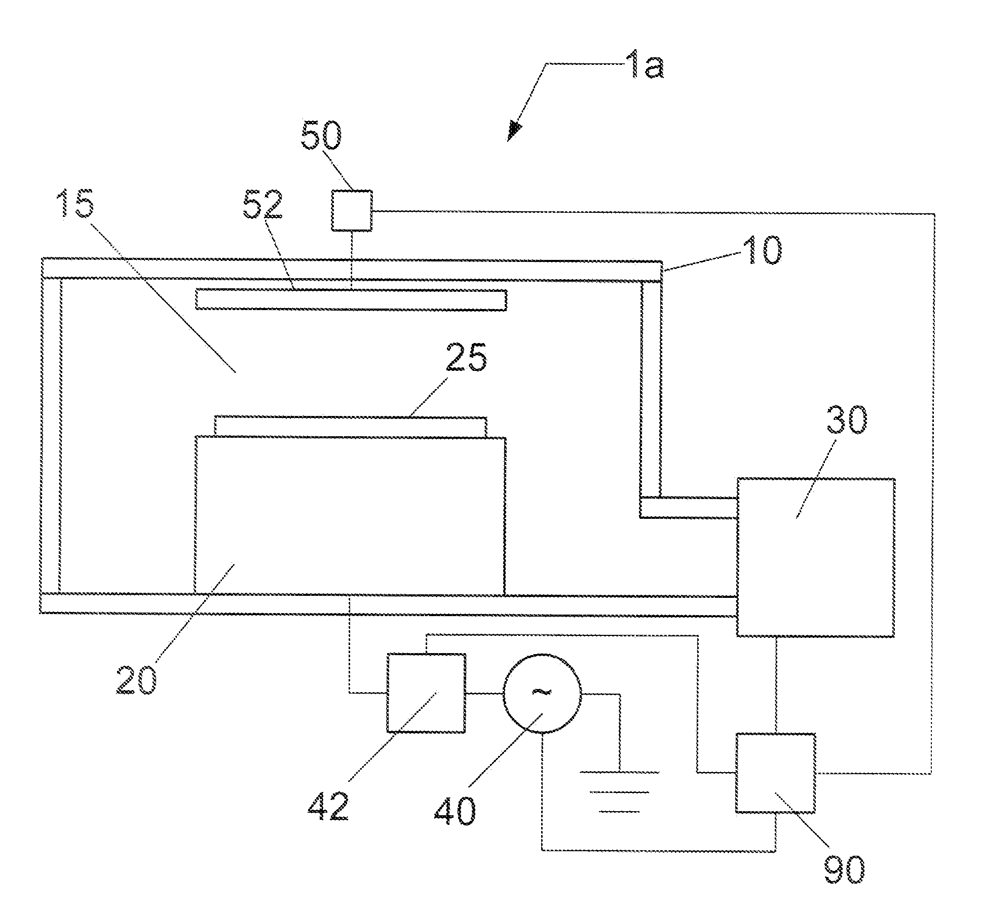
[0019]In the following description, for purposes of explanation and not limitation, specific details are set forth, such as a particular geometry of the plasma processing system and descriptions of various processes. However, it should be understood that the invention may be practiced in other embodiments that depart from these specific details.

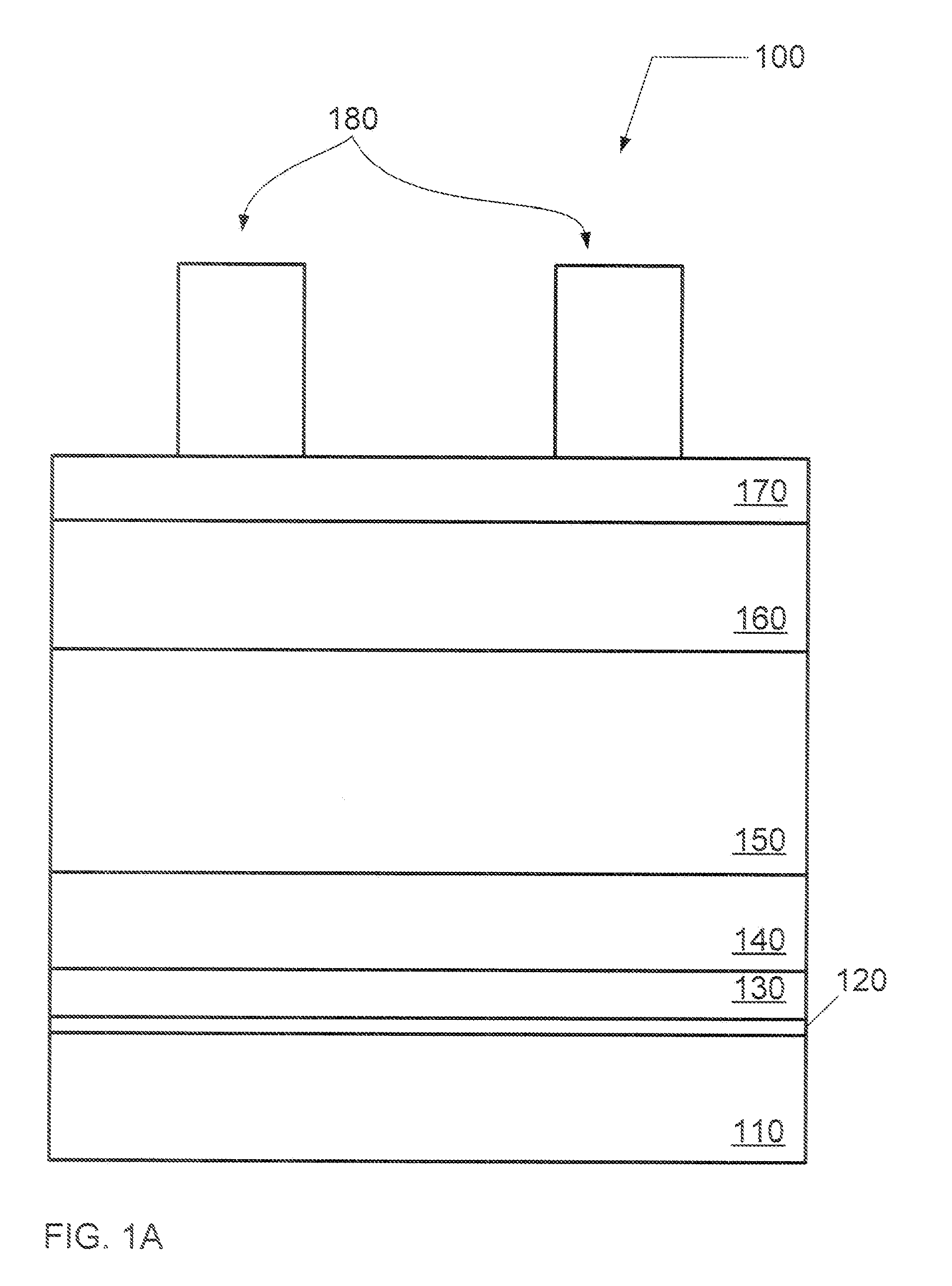
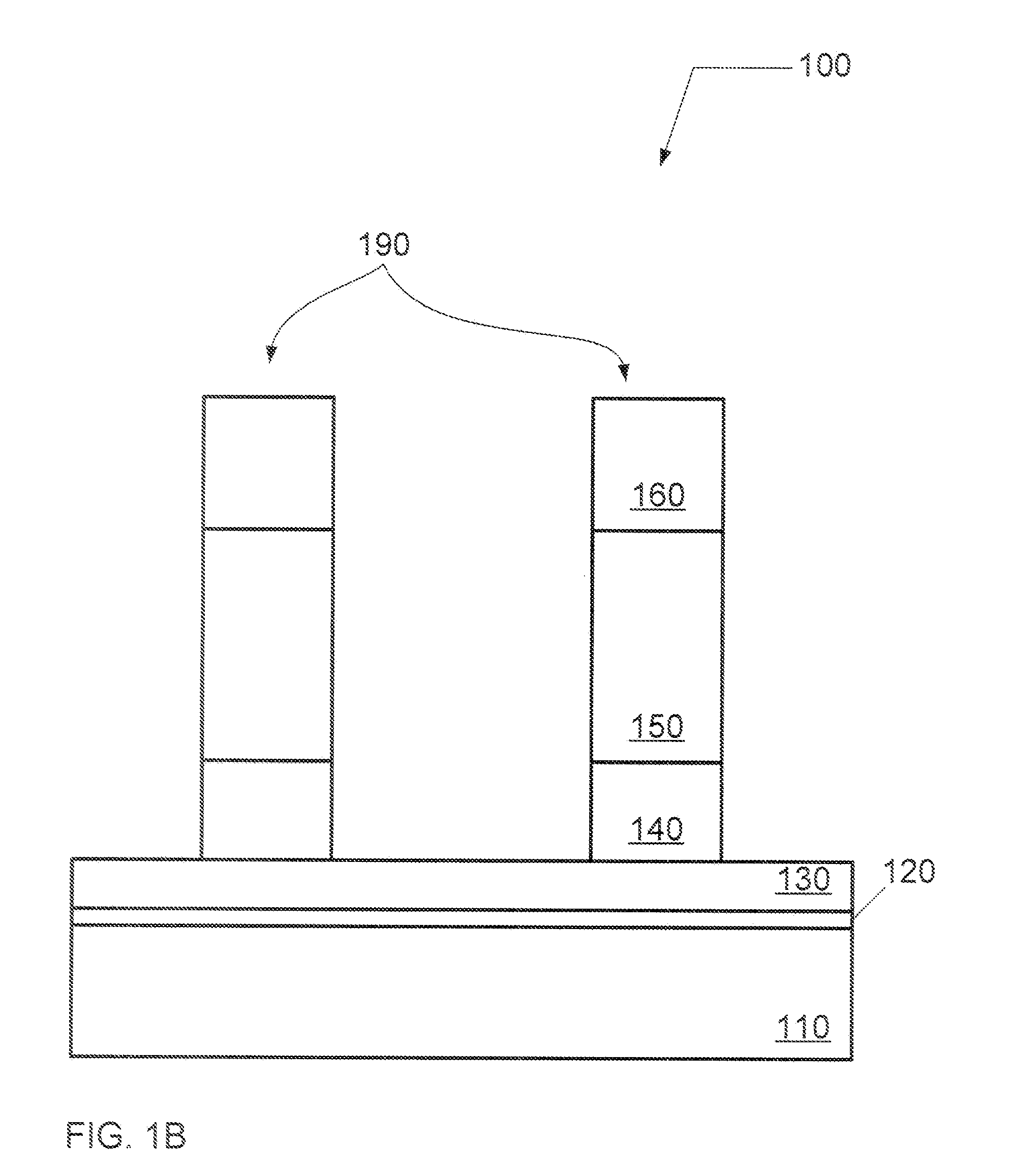
[0020]In material processing methodologies, pattern etching can comprise the application of a thin layer of light-sensitive material, such as photo-resist, to an upper surface of a substrate that is subsequently patterned in order to provide a mask for transferring this pattern to the underlying thin film on a substrate during etching. The patterning of the light-sensitive material generally involves exposure of the light-sensitive material to a geometric pattern of electro-magnetic (EM) radiation using, for example, a micro-lithography system, followed by the removal of the irradiated regions of the light-sensitive material (as in the case o...


PUM

PropertyMeasurementUnit
thickaaaaaaaaaa
sizeaaaaaaaaaa
sizeaaaaaaaaaa

Abstract

A method and system of etching a metal nitride, such as titanium nitride, is described. The etching process comprises introducing a process composition having a halogen containing gas, such as Cl2, HBr, or BCl3, and a fluorocarbon gas having the chemical formula CxHyFz, where x and z are equal to unity or greater and y is equal to 0 or greater.

Description

FIELD OF THE INVENTION[0001]The present invention relates to a method and system for etching a metal nitride layer on a substrate using a dry plasma process.BACKGROUND OF THE INVENTION[0002]As the size of semiconductor devices is reduced, process development and integration issues are key challenges for new gate stack materials including high-permittivity dielectric materials (also referred to herein as “high-k” materials).[0003]Dielectric materials featuring a dielectric constant greater than that of SiO2(k˜3.9) are commonly referred to as high-k materials. In addition, high-k materials may refer to dielectric materials that are deposited onto substrates (e.g., HfO2, ZrO2) rather than grown on the surface of the substrate (e.g., SiO2, SiNxOy). High-k materials may incorporate metallic silicates or oxides (e.g., Ta2O5(k˜26), TiO2(k˜80), ZrO2(k˜25), Al2O3(k˜9), HfSiO, HfO2(k˜25)).[0004]For front-end-of-line (FEOL) operations, in the near future, these high-k materials are contemplate...

Claims


Application Information

Patent Timeline
Patent Type & Authority Applications(United States)
IPC IPC(8): C23F1/00H01L21/306
CPCH01L21/32136H01L21/31122
Inventor TAKAHASHI, HIROYUKI
Owner TOKYO ELECTRON LTD
Why Eureka
Try Eureka