

Rotor Driving Control Device and Image Forming Apparatus
a control device and control device technology, applied in the direction of electric controllers, ignition automatic control, instruments, etc., can solve the problems of increasing the cost of structure, deteriorating image quality remarkably, and cumulative pitch error of gears, so as to reduce the fluctuation of the rotation period, improve the accuracy, and reduce the effect of rotational period
- Summary
- Abstract
- Description
- Claims
- Application Information
AI Technical Summary
Benefits of technology
Problems solved by technology
Method used
Image

Examples
first embodiment
Structure of DC Motor Driving System
[0082]One embodiment of the present invention will be explained by an image forming apparatus having the structure shown in FIG. 7. FIG. 7 is a structured diagram of a single driving control device in a driving control mechanism of photoconductor drum shown in FIG. 6.
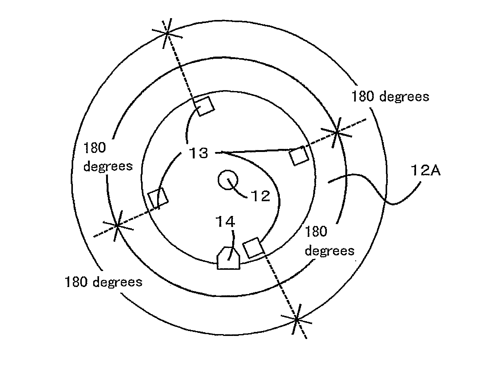
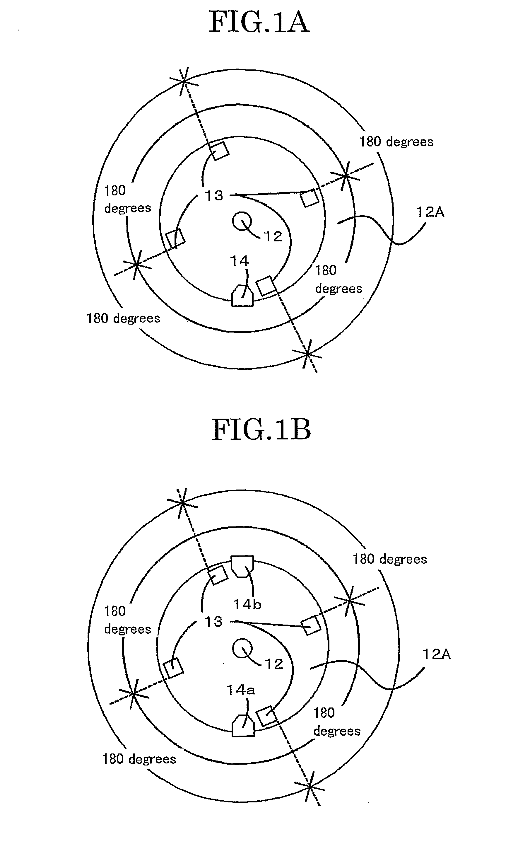
[0083]A DC servomotor 6 in FIG. 7 rotates and drives a drive gear 10 through a coupling 9a. The drive gear 10 transmits driving force to a driven gear 11. The driven gear 11 rotates a photoconductor drum 1 through couplings 9b, 9c. A rotation shaft 12 of the photoconductor drum 1 is provided with a rotation plate 12A having a detected portion 13. The rotation plate 12A rotates with the rotation shaft 12. In this case, when the detected portion 13 passes a detecting device 14, the detecting device 14 sends a pulse signal 15 to a control device 8. The control device 8 detects the rotation period fluctuation of the photoconductor drum 1, and sends a motor speed reference signal 16 toward...
second embodiment
[0118]In this embodiment, a method for matching a phase of rotation period fluctuation corresponding to one-revolution of a photoconductor drum of each color will be explained, in order to reduce a color shift generated by the rotation period fluctuation corresponding to one-revolution of the photoconductor drum of each color. This method independently rotates and drives the driving motor such that a plurality of photoconductor drums rotates by a predetermined phase difference with respect to the reference phase of the rotation period fluctuation of the photoconductor drum, adjusts the rotation period fluctuation phase corresponding to one-revolution of the photoconductor drum in the same pixel on the photoconductor drum of each color, superimposes the same pixel on a transfer paper such that the rotation period fluctuation phases match, and reduces the color shift of sub-scanning direction. The image quality can be, therefore, prevented from deteriorating. The phases are matched by...
third embodiment
[0127]In the first embodiment, the home position is set by the structure of the detection mechanism as shown in FIG. 19. In this embodiment, a reference detected portion is provided for setting a home position. The detection mechanism of the reference detected portion comprises the structure shown in FIG. 16, and the data processing thereof is shown in the flowchart in FIGS. 29A, 29B. In FIGS. 29A, 29B, the steps similar to the first embodiment are used till step S5. The passage times of T0, T1, T2 and T3 are stored in the memory for data incorporated in the control device 4, in order of passing the detected portion from the point passing the reference detected portion 17 as shown in FIG. 26 (step S6). The rotation period fluctuation calculating process corresponding to one-revolution of a drum is conducted by using the data of the passage times T0, T1, T2 and T3 (step S7).
[0128]The rotation period fluctuation calculating process corresponding to one-revolution of a drum has a funct...
PUM
 Abstract
Description
Claims
Application Information