Streaking correction signal generating circuit, streaking correction signal generating method, program, streaking correcting circuit, and imaging device

a technology of streaking correction and signal generating circuit, which is applied in the direction of color signal processing circuit, picture signal generator, solid-state device signal generator, etc., can solve the problems of loss of exposure time, inefficient video signal acquisition, and inability to detect correct streaking in real time, so as to enhance the accuracy of streaking correction and save memory capacity

Inactive Publication Date: 2008-09-25
SONY CORP
View PDF11 Cites 8 Cited by
  • Summary
  • Abstract
  • Description
  • Claims
  • Application Information

AI Technical Summary

Benefits of technology

[0019]The streaking correcting circuit may further include a correction gain generating unit configured to generate a correction gain to the signal level of the output signal of the image sensor; and a multiplying unit configured to multiply the streaking correction signal generated by the streaking correction signal generating unit by the correction gain generated by the correction gain generating unit. The subtracter may subtract the streaking correction signal multiplied by the correction gain by the multiplying unit from the output signal of the image sensor. A streaking component in a pixel portion changes depending on a signal level. As described above, by multiplying the streaking correction signal by the correction gain according to the signal level, the accuracy of streaking correction can be enhanced.
[0020]The correction gain generating unit may include a signal level detecting unit configured to detect a level of the output signal of the image sensor; and a memory configured to output a correction gain corresponding to the level detected by the signal level detecting unit. In this case, a correction gain corresponding to the signal level can be obtained from the memory without any processing. Alternatively, the correction gain generating unit may include a signal level detecting unit configured to detect a level of the output signal of the image sensor; a memory configured to output correction gains on both ends of a level range including the level detected by the signal level detecting unit; and a processing unit configured to calculate a correction gain corresponding to the level detected by the signal level detecting unit based on the level detected by the signal level detecting unit and the correction gains on the both ends output from the memory. In this case, the capacity of the memory can be saved.
[0021]With the above-described configuration, signal levels of respective lines of the horizontal light shield are detected by using an output signal of the horizontal light shield of the image sensor and a black level is detected by using an output signal of the vertical light shield of the image sensor. By subtracting the black level from each of the signal levels of the respective lines of the horizontal light shield, streaking correction signals of the respective lines are generated. Accordingly, the streaking correction signals can be obtained in real time without shielding the light receiving unit of the image sensor, so that streaking can be corrected in real time.

Problems solved by technology

In the technique described in Patent Document 1, the light receiving unit is shielded in order to obtain a streaking correction signal, and thus it may be impossible to detect streaking in real time and to correct streaking in real time.
Furthermore, shielding the light receiving unit frequently during shooting causes loss in exposure time, and thus video signals are obtained inefficiently.

Method used


Image

  • Streaking correction signal generating circuit, streaking correction signal generating method, program, streaking correcting circuit, and imaging device
  • Streaking correction signal generating circuit, streaking correction signal generating method, program, streaking correcting circuit, and imaging device
  • Streaking correction signal generating circuit, streaking correction signal generating method, program, streaking correcting circuit, and imaging device

Examples


Embodiment Construction

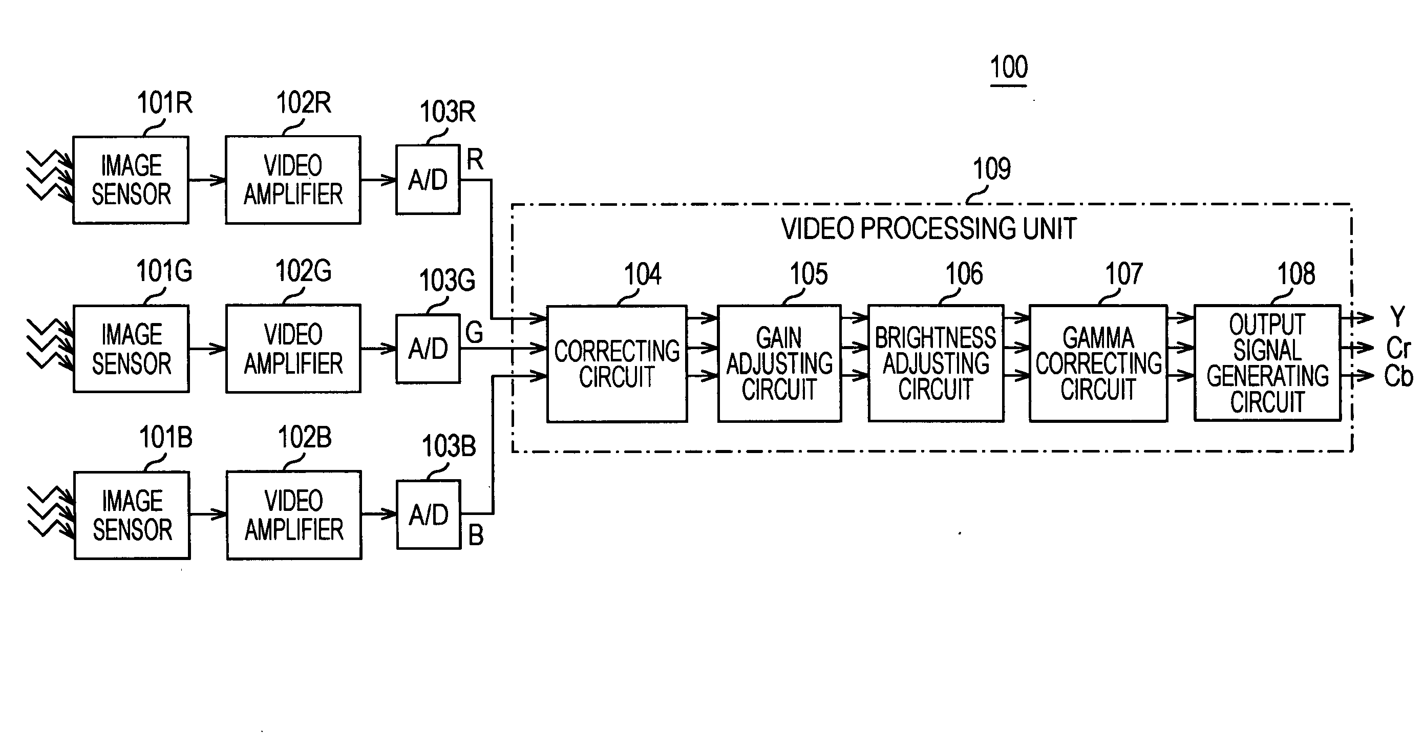
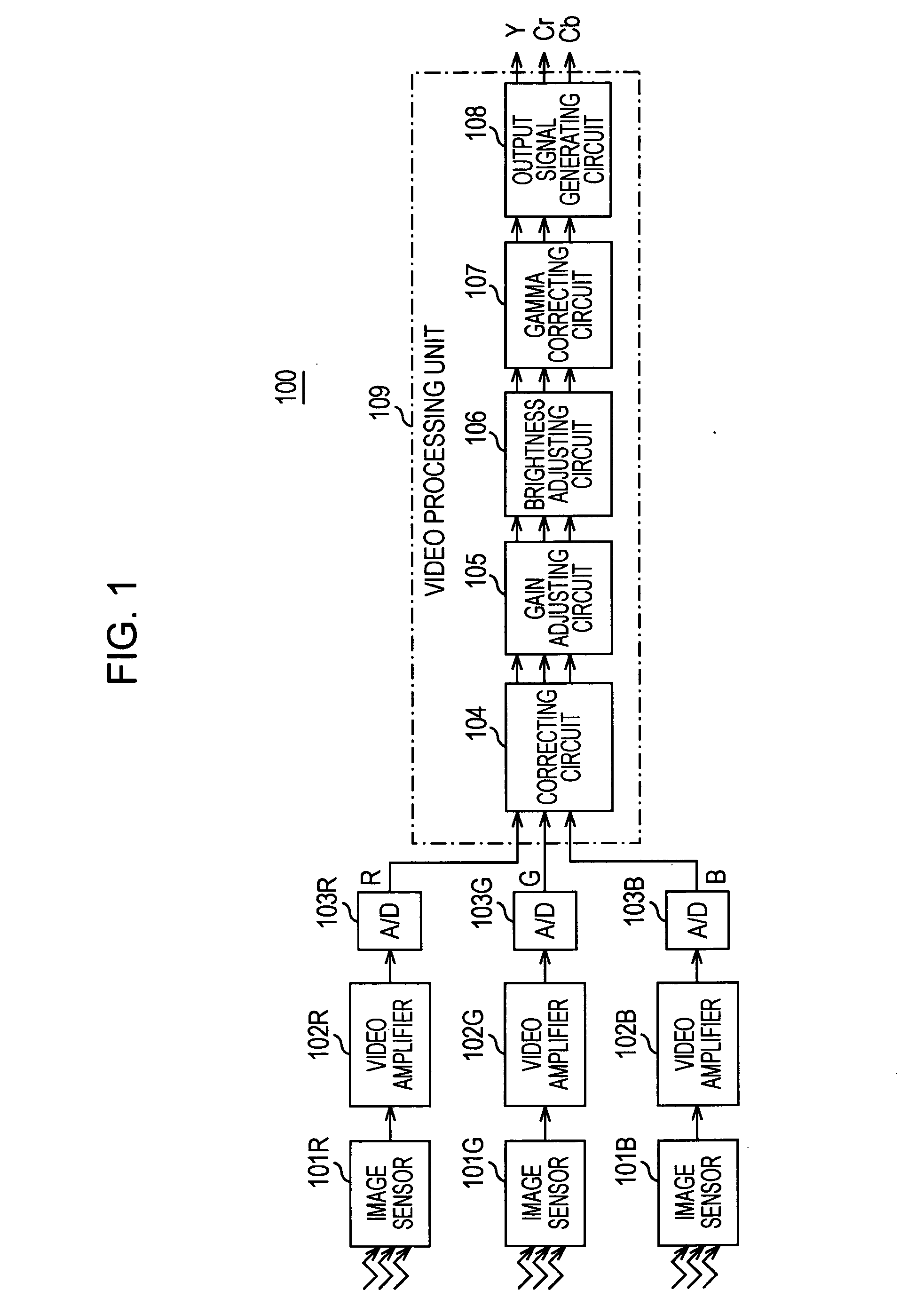
[0035]Hereinafter, an embodiment of the present invention is described with reference to the drawings. FIG. 1 illustrates an example of a configuration of an imaging device 100 according to an embodiment of the present invention. The imaging device 100 is a 3-CCD color imaging device. The imaging device 100 includes image sensors 101R, 101G, and 101B, video amplifiers 102R, 102G, and 102B, A / D converters 103R, 103G, and 103B, a correcting circuit 104, a gain adjusting circuit 105, a brightness adjusting circuit 106, a gamma correcting circuit 107, and an output signal generating circuit 108. The correcting circuit 104, the gain adjusting circuit 105, the brightness adjusting circuit 106, the gamma correcting circuit 107, and the output signal generating circuit 108 constitute a video processing unit 109.

[0036]The image sensors 101R, 101G, and 101B are used for red, green, and blue images, respectively. CCD or CMOS image sensors are used as the image sensors 101R, 101G, and 101B. The...


PUM


Abstract

A streaking correction signal generating circuit includes a light-shield waveform detecting unit configured to detect signal levels of respective lines in a horizontal light shield by using an output signal of the horizontal light shield of an image sensor; a black level detecting unit configured to detect a black level by using an output signal of a vertical light shield of the image sensor; and a subtracting unit configured to subtract the black level detected by the black level detecting unit from each of the signal levels of the respective lines in the horizontal light shield detected by the light-shield waveform detecting unit so as to generate streaking correction signals of the respective lines.

Description

CROSS REFERENCES TO RELATED APPLICATIONS[0001]The present invention contains subject matter related to Japanese Patent Application JP 2007-071699 filed in the Japanese Patent Office on Mar. 20, 2007, the entire contents of which are incorporated herein by reference.BACKGROUND OF THE INVENTION[0002]1. Field of the Invention[0003]The present invention relates to a streaking correction signal generating circuit, a streaking correction signal generating method, a program, a streaking correcting circuit, and an imaging device that are preferably applied to a solid-state imaging device including a CCD (charge-coupled device) image sensor or a CMOS (complementary metal oxide semiconductor) image sensor.[0004]More specifically, the present invention relates to a streaking correction signal generating circuit and so on enabling real-time correction of streaking by detecting signal levels of respective lines of a horizontal light shield by using an output signal of the horizontal light shield...

Claims


Application Information

Patent Timeline
Patent Type & Authority Applications(United States)
IPC IPC(8): H04N5/217H04N5/335H04N5/361H04N5/369H04N5/378
CPCH04N5/3595H04N9/045H04N5/3658H04N5/361H04N25/625H04N25/63H04N25/677H04N23/84H04N25/62H04N25/60
Inventor KINOSHITA, YUKIHIROTAKAHASHI, KAZUSHIGEHARA, MANABU
Owner SONY CORP
Why Eureka
Try Eureka