Magnetoresistance effect device, magnetic lamination structural body, and manufacture method for magnetic lamination structural body

Inactive Publication Date: 2008-09-25
FUJITSU LTD
View PDF4 Cites 27 Cited by
  • Summary
  • Abstract
  • Description
  • Claims
  • Application Information

AI Technical Summary

Benefits of technology

[0014]According to an aspect of an embodiment, there

Problems solved by technology

It is therefore difficult to improve a recording density by shortening the bit length Lb.
If the tunneling barrier layer is made thin to lower an area resistance RA of the TMR device, magnetostatic interaction between the reference layer and magnetization free layer becomes large because of surface irregularity of the r

Method used


Image

  • Magnetoresistance effect device, magnetic lamination structural body, and manufacture method for magnetic lamination structural body
  • Magnetoresistance effect device, magnetic lamination structural body, and manufacture method for magnetic lamination structural body
  • Magnetoresistance effect device, magnetic lamination structural body, and manufacture method for magnetic lamination structural body

Examples


first embodiment

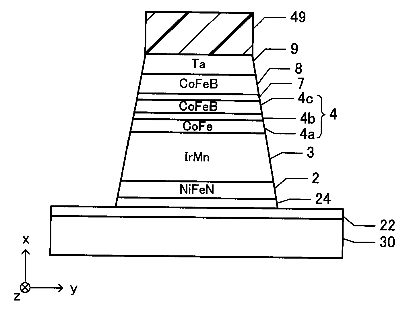
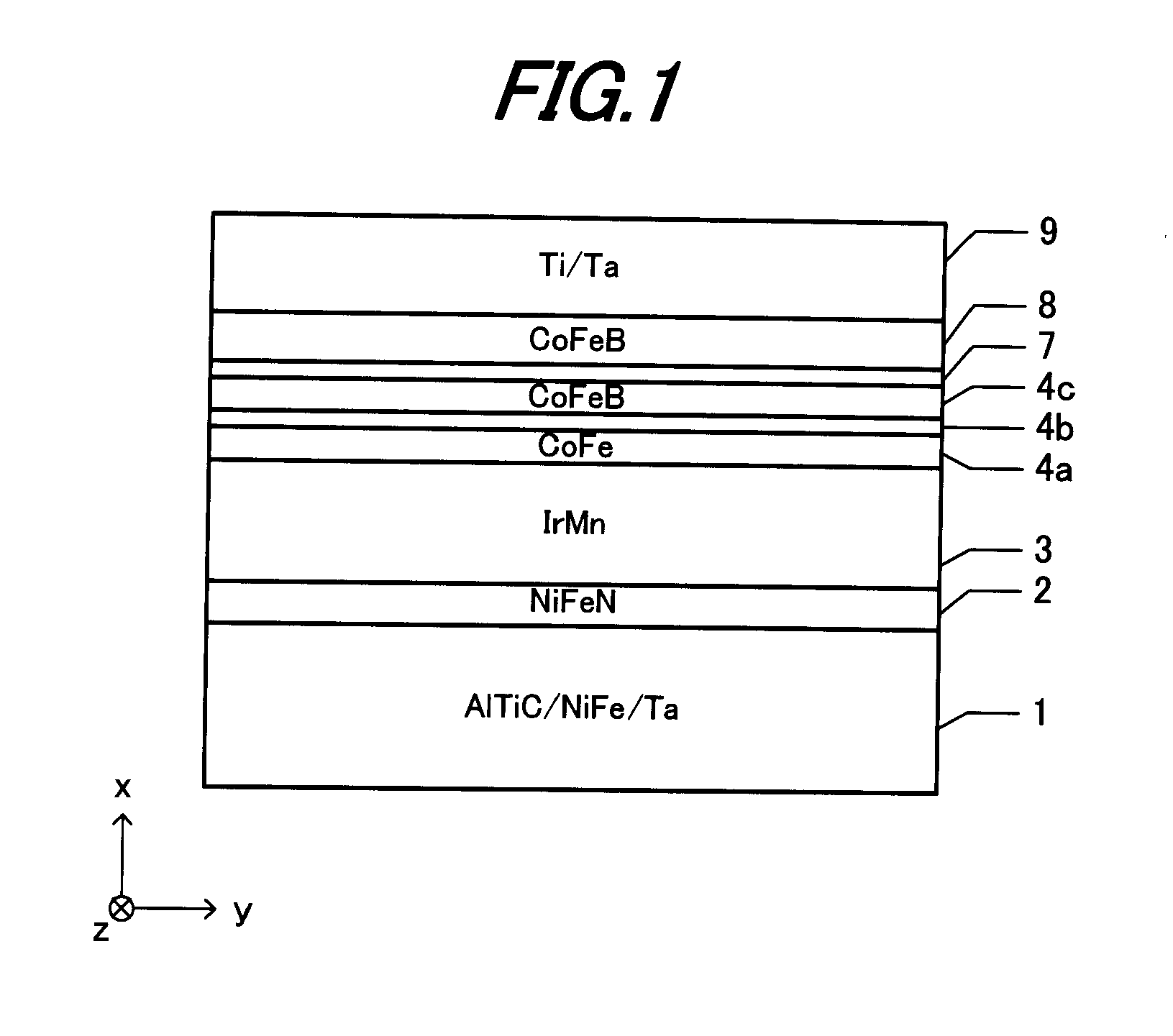
[0045]FIG. 1 is a cross sectional view of a magnetoresistance effect device according to the On a support substrate 1, an underlying layer 2, a pinning layer 3, a pinned layer 4a, a nonmagnetic intermediate layer 4b, a reference layer 4c, a tunneling barrier layer (nonmagnetic layer) 7, a free layer 8 and a cap layer 9 are stacked in this order. For example, the support substrate 1 has a lamination structure that a NiFe layer and a Ta layer are laminated in this order on an Al2O3—TiC substrate.

[0046]The underlying layer 2 is made of NiFeN and has a thickness of 3 nm, for example. The NiFeN film can be formed by reactive sputtering using NiFe as a target and using Ar and N2 as sputtering gas. A target of Ni and Fe added with a third element may be used. A usable third element may be Co, Cr, Cu or the like. This film may be formed by cosputtering. The pinning layer 3 is made of IrMn and has a thickness of 7 nm, for example.

[0047]The pinned layer 4a is made of ferromagnetic material s...

second embodiment

[0064]FIG. 6A is a cross sectional view of a magnetoresistance effect device according to the Formed on a support substrate 1 are an underlying layer 2, a pinning layer 3, a reference layer 4c, a tunneling barrier layer 7, a free layer 8 and a cap layer 9 laminated in this order. The support substrate 1 has a structure that a Ta layer having a thickness of 3 nm is formed on a silicon substrate whose surface is etched to be planarized. The reference layer 4c is made of CoFe and has a thickness of 2.0 nm. The cap layer 9 has a three-layer structure that a Ta layer having a thickness of 5 nm, a Cu layer having a thickness of 10 nm and an Ru layer having a thickness of 10 nm are stacked in this order. The underlying layer 2, pinning layer 3, tunneling barrier layer 7 and free layer 8 each have the same structure as that of a corresponding layer of the magnetoresistance effect device shown in FIG. 1.

[0065]For the purposes of comparison, a sample was formed having the reference layer 4c ...

third embodiment

[0075]FIG. 8A is a front view of a face opposed to a recording medium of a magnetic head according to the An xyz orthogonal coordinate system is defined in such a manner that an xy plane is defined on the face opposed to a recording medium, x-axis is parallel to a trailing direction, y-axis is parallel to a track width direction, z-axis is perpendicular to the face opposed to a recording medium. FIG. 8B is a cross sectional view parallel to the zx plane of the magnetic head.

[0076]On a substrate 30, a reading element portion 20 and a recording element portion 40 are laminated in this order. The reading element portion 20 includes a lower magnetic shielding layer 22, a magnetoresistance effect film 21 and an upper magnetic shielding layer 23. The recording element portion 40 includes a main magnetic pole 41, a main magnetic pole auxiliary layer 42, an auxiliary magnetic pole 43 and a coupling portion 45. The main magnetic pole 41, main magnetic pole auxiliary layer 42, auxiliary magn...


PUM

PropertyMeasurementUnit
Thicknessaaaaaaaaaa
Thicknessaaaaaaaaaa
Thicknessaaaaaaaaaa

Abstract

An underlying layer (2) made of NiFeN is disposed over the principal surface of a substrate. A pinning layer (3) made of antiferromagnetic material containing Ir and Mn is disposed on the underlying layer. A reference layer (4c) made of ferromagnetic material whose magnetization direction is fixed through exchange-coupling with the pinning layer directly or via another ferromagnetic material layer, is disposed over the pinning layer. A nonmagnetic layer (7) made of nonmagnetic material is disposed over the reference layer. A free layer (8) made of ferromagnetic material whose magnetization direction changes in dependence upon an external magnetic field, is disposed over the nonmagnetic layer.

Description

CROSS REFERENCE TO RELATED APPLICATION[0001]This application is based on and claims priority of Japanese Patent Application No. 2007-072280 filed on Mar. 20, 2007, the entire contents of which are incorporated herein by reference.BACKGROUND OF THE INVENTION[0002]A) Field of the Invention[0003]The present invention relates to a magnetoresistance effect device having a pinning layer made of antiferromagnetic material containing Ir and Mn, a magnetic lamination structural body and a manufacture method for a magnetic lamination structural body.[0004]B) Description of the Related Art[0005]An exchange coupling film having a lamination structure consisting of an antiferromagnetic film and a ferromagnetic film is used to fix a magnetization direction of a ferromagnetic film used in a reading device of a hard disk drive (HDD) or a magnetoresistance effect type random access memory (MRAM).[0006]FIG. 12 is a partial perspective view of a HDD reading device and a magnetic recording medium. An x...

Claims


Application Information

Patent Timeline
IPC IPC(8): G11B5/33C23C14/00
CPCB82Y10/00B82Y25/00G01R33/093G11C11/15G11B5/3909G11B5/3967G11B5/3906G11C11/16H10N50/10H10N50/01G11B5/39
Inventor IBUSUKI, TAKAHIROSATO, MASASHIGEUMEHARA, SHINJIRO
Owner FUJITSU LTD
Why Eureka
Try Eureka