Devices for treating the spine

a technology for treating the spine and discs, applied in the field of apparatus and methods employed in minimally invasive surgical procedures, can solve the problems of affecting the patient's recovery, disrupting and disturbing the tissue surrounding the surgical site, and changing the extracellular matrix pattern of the disc, so as to and increase the dimensional aspect of the structure in situ

Active Publication Date: 2008-09-25
SPINAL ELEMENTS INC
View PDF100 Cites 97 Cited by
  • Summary
  • Abstract
  • Description
  • Claims
  • Application Information

AI Technical Summary

Benefits of technology

[0024]In another aspect, a tissue distraction device is provided by the present invention comprising a first elongated member, a second elongated member, and an augmenting elongated member, with the first elongated member adjacent the second elongated member. The first and second elongated members are insertable between tissue layers to define a structure in situ having a dimensional aspect in a direction extending between the tissue layers. An augmenting elongated member is operatively cooperative with the first and second members to increase the dimensional aspect of the structure in situ.
[0025]In accordance with another aspect of the invention a method is provided for separating tissue layers. The method includes inserting a first elongated member between tissue layers to form a structure in situ with a dimensional aspect in a direction extending between the tissue layers. The method further includes inserting an augmenting elongated member between tissue layers, the augmenting elongated member cooperating with the first member to increase the dimensional aspect of the structure in situ and to cause spreading of the tissue layers.
[0026]In accordance with yet a further aspect of the present invention a method of separating tissue layers is provided that comprises inserting first and second elongated members. The method includes inserting first elongated member and the second elongated member between tissue layers to form a structure in situ with a dimensional aspect in a direction extending between the tissue layers. The method further includes inserting and augmenting elongated member between tissue layers the augmenting elongated member cooperating with the first and second elongated members to increase the dimensional aspect of the structure in situ and to cause spreading of the tissue layers.

Problems solved by technology

Developmental irregularities, trauma, tumors, stress and degenerative wear can cause defects in the spinal column for which surgical intervention is necessary.
Such invasive surgical techniques often disrupt and disturb tissue surrounding the surgical site to the detriment of the patient.
Genetic and biochemical causes can result in changes in the extracellular matrix pattern of the disc and a decrease in biosynthesis of extracellular matrix components by the cells of the disc.
With a loss of water content, the nucleus becomes desiccated resulting in a decrease in internal disc hydraulic pressure, and ultimately to a loss of disc height.
This loss of disc height can cause the annulus to buckle with non-tensile loading and the annular lamellae to delaminate, resulting in annular fissures.
The weight of the person generates a compressive load on the discs, but this load is not uniform during typical bending movements.
On the local (or cellular, level) decreased disc height results in increased pressure in the nucleus, which can lead to a decrease in cell matrix synthesis and an increase in cell necrosis and apoptosis.
In addition, increases in intra-discal pressure create an unfavorable environment for fluid transfer into the disc, which can cause a further decrease in disc height.
With decreasing height of the disc, the facet joints bear increasing loads and may undergo hypertrophy and degeneration, and may even act as a source of pain over time.
Decreased stiffness of the spinal column and increased range of motion resulting from loss of disc height can lead to further instability of the spine, as well as back pain.
This decrease may lead to spinal nerve impingement, with associated radiating pain and dysfunction
The discs that must bear additional loading are now susceptible to accelerated degeneration and compromise, which may eventually propagate along the destabilized spinal column.
However, the sudden decrease in disc volume caused by the surgical removal of the disc or disc nucleus may increase the local and global problems noted above.
During a total discectomy, a substantial amount (and usually all) of the volume of the nucleus pulposus is removed and immediate loss of disc height and volume can result.
Even with a partial discectomy, loss of disc height can ensue.
A challenge in the use of a posterior procedure to install spinal prosthesis devices is that a device large enough to contact the end plates and expand the space between the end plates of the same or adjacent vertebra must be inserted through a limited space.
In the case of procedures to increasing intervertebral spacing, the difficulties are further increased by the presence of posterior osteophytes, which may cause “fish mouthing” or concavity of the posterior end plates and result in very limited access to the disc.
A further challenge in degenerative disc spaces is the tendency of the disc space to assume a lenticular shape, which requires a relatively larger implant than often is easily introduced without causing trauma to the nerve roots.
The size of rigid devices that may safely be introduced into the disc space is thereby limited.
While cages of the prior art have been generally successful in promoting fusion and approximating proper disc height, typically these cages have been inserted from the posterior approach, and are therefore limited in size by the interval between the nerve roots.
Further, it is generally difficult, if not impossible to implant from the posterior approach a cage that accounts for the natural lordotic curve of the lumber spine.
However, despite the use of minimally invasive techniques, the implantation of cage devices for treating the spine typically involves nerve root retraction, an inherently high risk procedure.
However if a device is visible using X-ray technology, then the device can interfere with the detection and monitoring of spinal tissues, such as bone growing into the disc space after a vertebral fusion procedure.

Method used


Image

  • Devices for treating the spine
  • Devices for treating the spine
  • Devices for treating the spine

Examples


Embodiment Construction

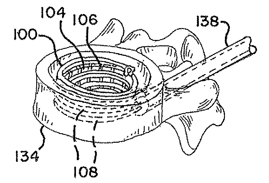
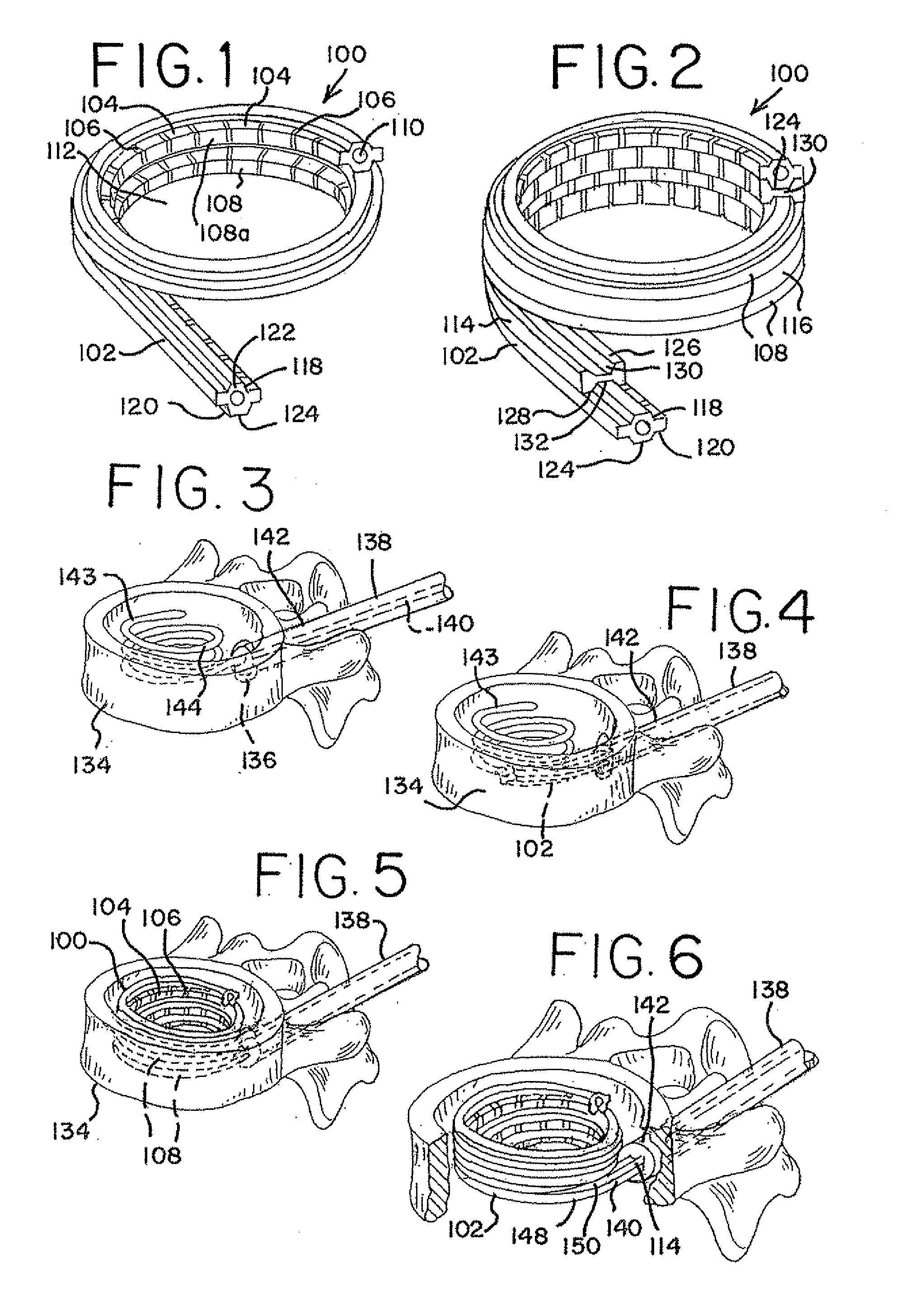
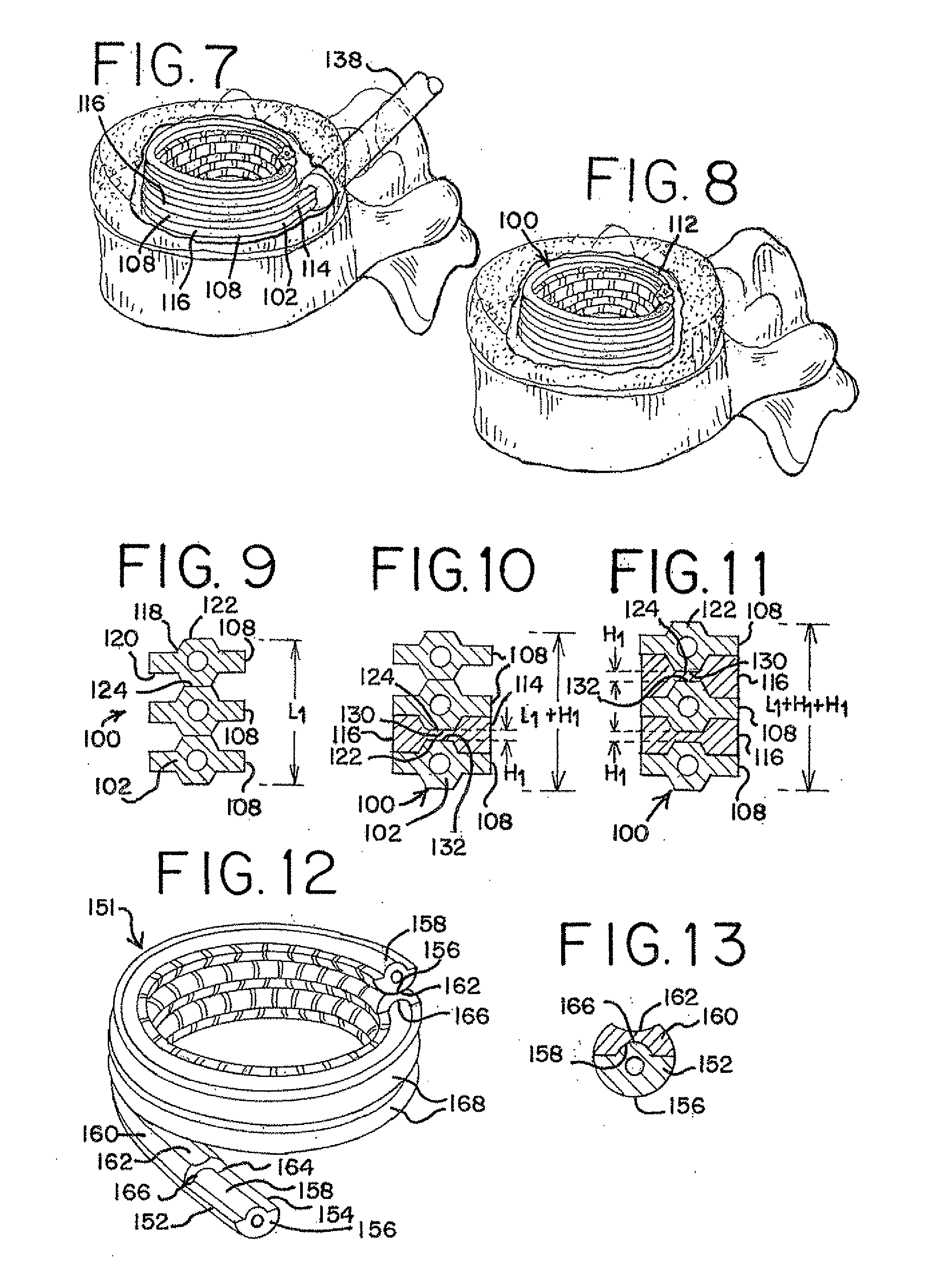
[0099]The devices and methods of the present invention provide multiple features of distraction devices, distraction device support structures and deployment systems that can be used to actively separate tissue layers by engaging them and forcing them apart, or to support the separation of tissue layers separated by the distraction device itself or by other devices or processes or a combination of these.

[0100]As used herein, the terms “distraction device” and “distraction device support structure” are intended to have a general meaning and is not limited to devices that only actively separate tissue layers, only support tissue layers or only both actively separate and support tissue layers. For example, the distraction device and support structure in general can be used to actively separate layers of tissue and then be removed after such separation, or the distraction device and the support structure could be used to support layers of tissue that have been previously separated by a ...


PUM


Abstract

Method and apparatus are disclosed for distracting tissue and particularly spinal tissue. The device and method may include insertion of at least one elongated member and an augmenting member to form a structure between the tissues to be distraction, such that a dimensional aspect of the structure is augmented upon movement of the augmenting structure.

Description

[0001]The present application is a continuation-in-part of U.S. patent application Ser. No. 11 / 464,782, a continuation-in-part of U.S. patent application Ser. No. 11 / 464,790, a continuation-in-part of U.S. patent application Ser. No. 11 / 464,793, a continuation-in-part of U.S. patent application Ser. No. 11 / 464,807, a continuation-in-part of U.S. patent application Ser. No. 11 / 464,812 and a continuation-in-part of U.S. patent application Ser. No. 11 / 464,815, all of which were filed on Aug. 15, 2006, and claim the benefit of U.S. Provisional Application No. 60 / 708,691, filed Aug. 16, 2005, U.S. Provisional Application No. 60 / 738,432, filed Nov. 21, 2005 and U.S. Provisional Application No. 60 / 784,185, filed Mar. 21, 2006, all of the above are incorporated herein by reference. In addition to claiming the benefit of the filing dates of all of the above regular and provisional applications, the present application also claims the benefit of U.S. Provisional Patent Application No. 60 / 890,...

Claims


Application Information

Patent Timeline
Patent Type & Authority Applications(United States)
IPC IPC(8): A61B17/58A61F2/44
CPCA61B17/8852A61B17/7094A61F2/44A61F2/4455A61F2/4611A61F2002/2835A61F2002/30092A61F2002/30153A61F2002/30235A61F2002/30263A61F2002/30289A61F2002/30462A61F2002/3052A61F2002/30594A61F2002/30601A61F2002/30677A61F2002/30772A61F2002/448A61F2002/4627A61F2002/4635A61F2002/4683A61F2002/4688A61F2210/0014A61F2220/0025A61F2220/0075A61F2230/0019A61F2230/0069A61F2230/0084A61F2230/0091A61F2310/00293A61F2/442A61B2017/0256B33Y80/00A61F2210/0071A61F2002/30579A61F2002/4677A61F2/4425A61F2002/3008H05K999/99
Inventor SCHALLER, LAURENTMCGRATH, TIMOTHYCONNOLLY, RYANNEEDLEMAN, DAVIDGOLDEN, STEVENASHLEY, JOHNLEE, JAMESEMERY, JEFFREYBURLEY, J. BROOK
Owner SPINAL ELEMENTS INC
Why Eureka
Try Eureka